Wiring the rbm to a drive system, 2090-xb33-xx block diagram, Attention – Rockwell Automation 2090-XBxxx Resistive Brake Module Installation Instructions User Manual
Page 11
Publication 2090-IN009F-EN-P — November 2004
Resistive Brake Module Installation Instructions
11
Wiring the RBM to a Drive
System
This section provides wiring instructions for the Resistive Brake Module
within a general drive system. Refer to Related Documentation on page 24 for
installation and integration instructions containing wiring information specific
to a drive system. In addition:
• Figure 1 on page 5 depicts suggested routing of RBM wiring within the
dirty noise zone.
• Figure 6 and Figure 7 on page 10 show connector locations and provides
pinouts for each RBM connector.
• Recommended wire sizes and torque values for I/O signal wires and
power wires are provided in RBM Wiring Requirements on page 13 and in
Specifications.
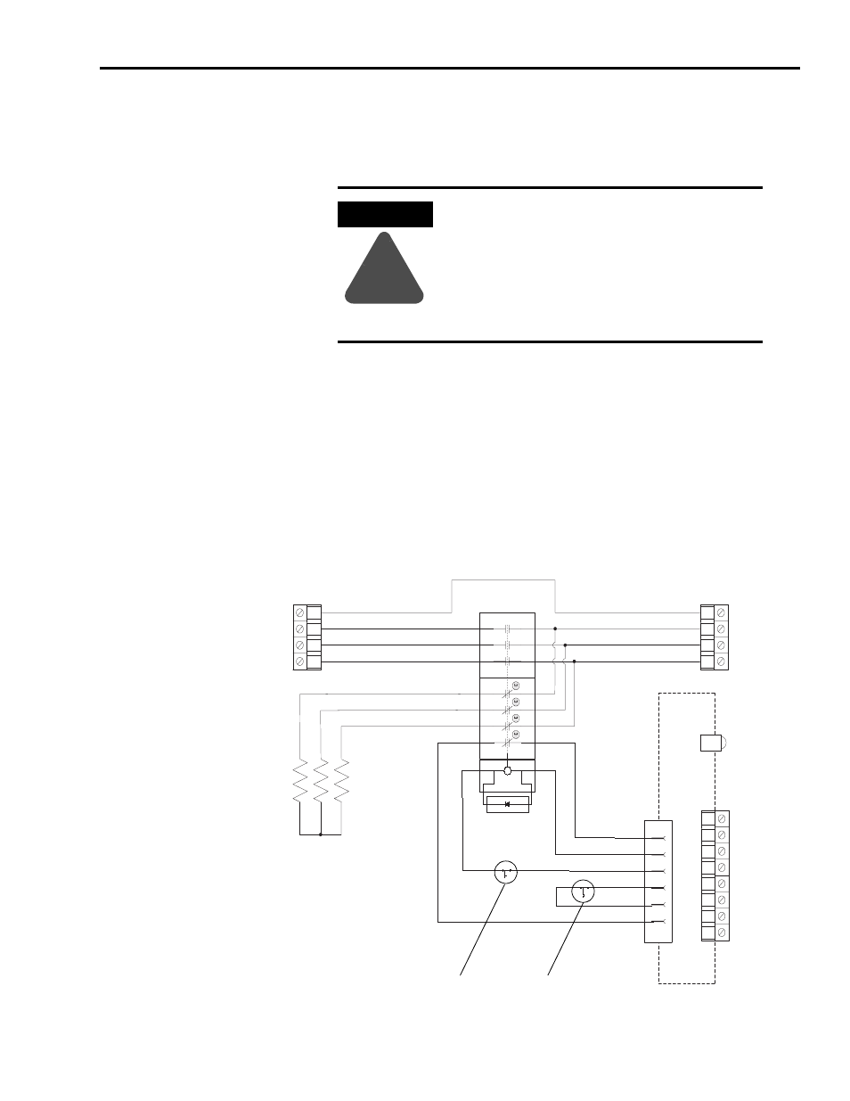
Figure 8
2090-XB33-xx Resistive Brake Module Block Diagram
ATTENTION
!
To comply with UL 508C, a Resistive Brake Module
must be protected upstream by a 2.5 kV overvoltage
control device.
Kinetix and Ultra servo drives from Rockwell
Automation meet this requirement. For additional
drive applicability, please consult your Allen-Bradley
representative.
1
2
3
4
5
6
11
12
21
22
31
32
41
42
A1
A2
D1
1
2
3
4
1
2
3
4
1
2
3
4
5
6
7
8
Ground
TB1 - Drive
Connection
W Drive
V Drive
U Drive
Ground
TB2 - Motor
Connection
W Motor
V Motor
U Motor
TS_21
TB3 - I/O
TS_22
CONSTAT_41
CONSTAT_42
SHIELD
COIL_A1
COIL_A2
SHIELD
Status LED
T2 (Warning)
T1 (Fault)
Printed
Circuit
Board
100S-C23
CR1