Understanding your resistive brake module – Rockwell Automation 2090-XBxxx Resistive Brake Module Installation Instructions User Manual
Page 3
Publication 2090-IN009F-EN-P — November 2004
Resistive Brake Module Installation Instructions
3
Understanding Your
Resistive Brake Module
The RBM provides an alternative way to brake a drive system. It provides the
control system engineer with the opportunity to design safety controls into a
machine’s drive system that have two key features:
• Physically and electrically separate the drive power output from its
corresponding motor.
• Reduce the stopping time for a motor and its load should a failure occur to
the machine in which it is installed.
Drive commands are the preferred and quickest way to bring a drive system to
a controlled stop. The RBM provides a non-mechanical method for braking a
drive system, by draining motor energy through a resistive load that dissipates
the energy as waste heat.
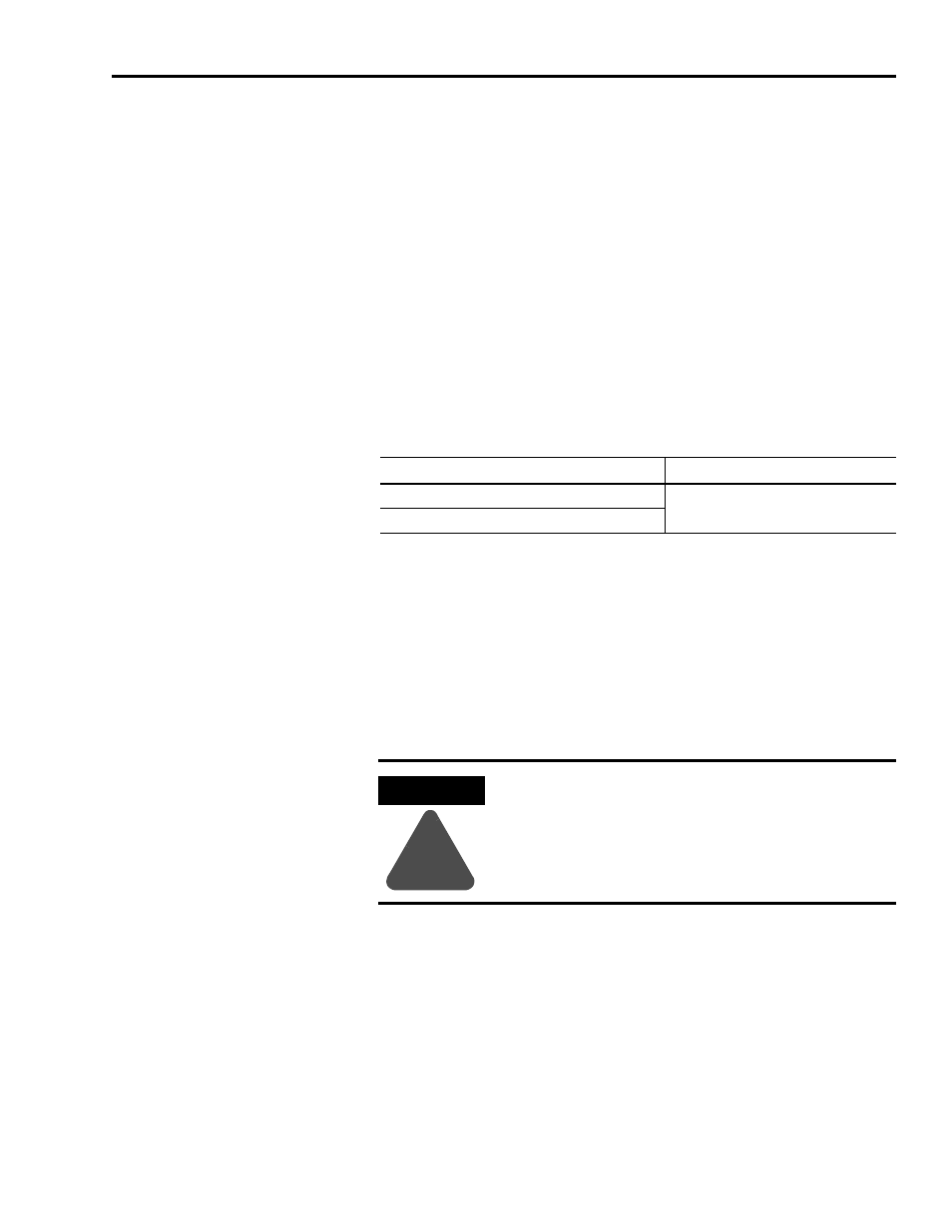
The RBM can resistively brake a motor once per minute with the following
inertia mismatch:
Refer to the Motion Control Selection Guide (publication GMC-SG001x-EN-P)
for details on applicable RBM and motor combinations.
A contactor in the RBM physically and electrically separates the motor leads
from the drive output, and provides status outputs to a customer designed
safety circuit. To maximize the stopping speed, braking resistors are sized to
match the motor and load for a specific axis of the drive system. The resistors
are placed across the phases and brake the motor by quickly dissipating the
energy stored there.
Resistive Brake Module
Inertia Mismatch
2090-XB33-16, 2090-XB33-32
2090-XB120-01, 2090-XB120-03, 2090-XB120-06
ATTENTION
!
Implementation of safety circuits and risk assessment is the
responsibility of the machine builder. Reference
international standards EN1050 and EN954 estimation and
safety performance categories. For more information refer
to Understanding the Machinery Directive (publication
SHB-900).