Rbm wiring requirements, L_a1, L_a2 – Rockwell Automation 2090-XBxxx Resistive Brake Module Installation Instructions User Manual
Page 13
Publication 2090-IN009F-EN-P — November 2004
Resistive Brake Module Installation Instructions
13
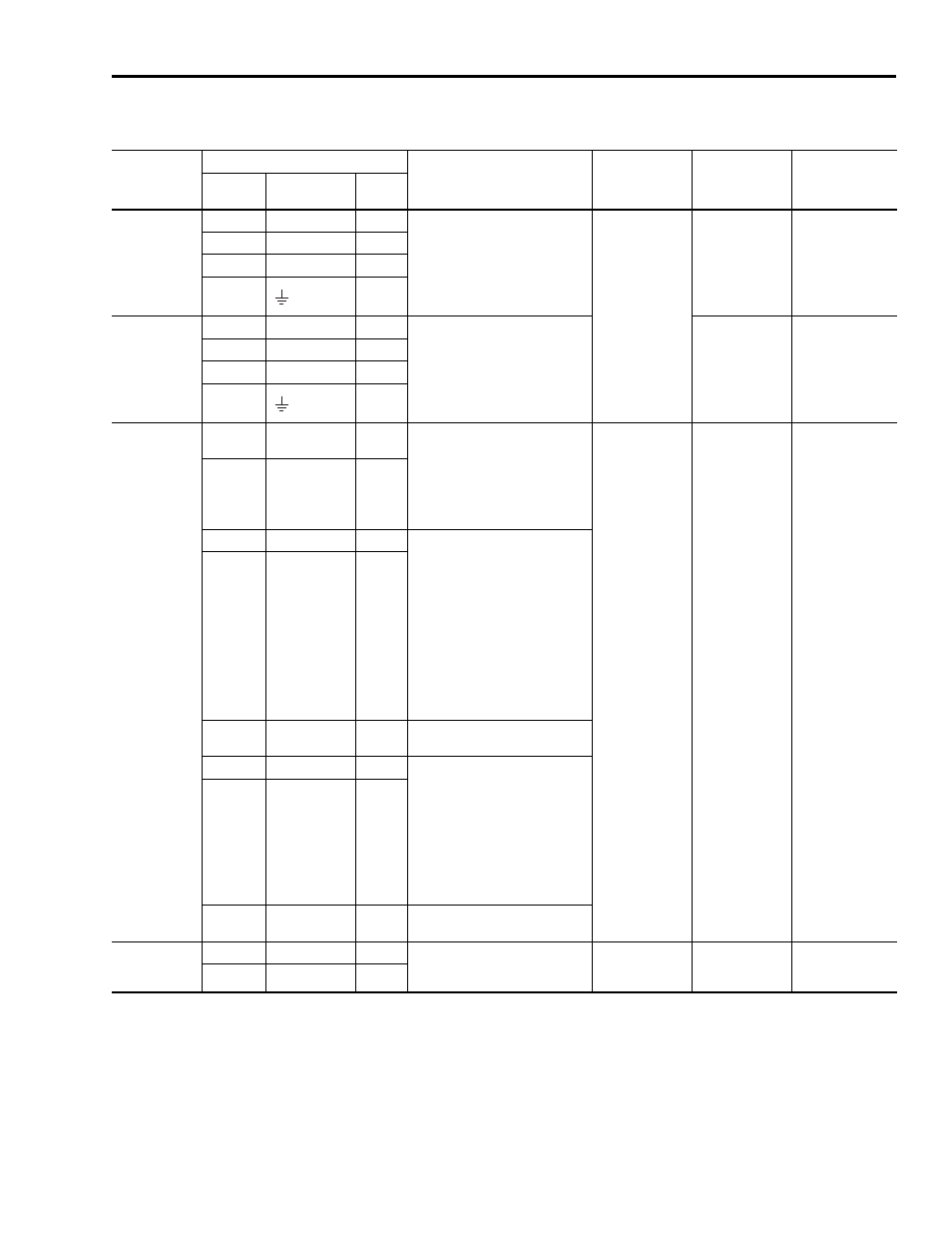
RBM Wiring Requirements
Connector
Connects to:
Description and Usage
Recommended
Wire Size
4
mm
2
(AWG)
Insulation Strip
Length
mm (in.)
Torque Value
Nm (lb-in.)
Terminal
-Pin
Signal
Input/
Output
Drive
Connection
1
TB1-1
U Drive
–
230/460V power input from drive
Minimum gauge
for power cable
is dependent on
the motor/drive
combination,
2090-XB33-xx
6 (10) maximum
2090-XB120-xx:
25 (3) maximum
2090-XB33-xx
10.0
(0.375)
2090-XB120-xx:
16.0
(0.63)
2090-XB33-xx:
0.5 - 0.6
(4.4 - 5.3)
2090-XB120-xx:
2.5 - 2.9
(22.1 - 25.7)
TB1-2
V Drive
–
TB1-3
W Drive
–
TB1-4
2
–
Motor
Connection
1
TB2-1 U
Motor
–
230/460V power output to motor
2090-XB33-xx
10.0
(0.375)
2090-XB120-xx:
16.0
(0.63)
2090-XB33-xx:
0.5 - 0.6
(4.4 - 5.3)
2090-XB120-xx:
2.5 - 2.9
(22.1 - 25.7)
TB2-2 V
Motor
–
TB2-3 W
Motor
–
TB2-4
2
–
I/O Signals
5,6
TB3-1
TS_21
In
RBM output with integral thermal
warning
Customer use of this auxiliary
contact may include:
• PLC or control string input that
RBM is nearing its thermal
limit
1.5 - 0.08
(16 - 28)
6.0
(0.25)
0.22 - 0.25
(1.9 - 2.2)
TB3-2 TS_22
Out
TB3-3
CONSTAT_41
In
RBM output of a normally closed
contact
(Closed = motor disconnected
from drive)
Customer use of this auxiliary
contact may include:
• PLC input connection,
indicating RBM contactor
status
• Safety relay input for safety
string
• Part of RBM safety string for
mechanical redundancy
TB3-4 CONSTAT_42 Out
TB3-5 SHIELD
3
–
I/O Shield internally terminated at
chassis ground
TB3-6
COIL_A1
In
RBM contactor coil with integral
thermal fault. Applying 24V Coil
Power picks-up the contactor,
which connects drive power to
motor leads (i.e., motor rotates).
Customer use may include:
• Control from a safety relay
output or signal relay output
indicating system is clear for
rotation
TB3-7 COIL_A2
Out
TB3-8 SHIELD
3
–
I/O Shield internally terminated at
chassis ground
230V Power
7
(2090-XB120-x
x only)
TB4-1
L1
–
Auxiliary power input from
external 230 VAC power source
(2090-XB120-xx only)
4.0 - 0.2
(10 - 24)
7.0
(0.28)
0.5 - 0.6
(4.4 - 5.3)
TB4-2 L2
–
1 Connectors are keyed to prevent misconnection of power interface cables to and from the RBM.
2 Ground connection for the motor cable passes through the drive and motor connectors.
Cable shielding must be grounded to the chassis via the spring-loaded cable clamps.
3 I/O Shield terminations are connected internally to chassis ground.
4 Wire supplied by user should be stranded copper with 75° C (167° F) minimum rating. An earth ground connection is required for safe and proper operation. Local agency
rules apply.
5 For additional contactor applications, refer to the Allen-Bradley Safety Product Catalog (Publication S114-CA001A-EN-P).
6 I/O is powered by an external 24V (22.4 - 26.4), 0.5A power supply.
7 Provided by an external 230V (207 - 253), 1A power supply.