Auxiliary contact specifications, Accessory equipment – Rockwell Automation 2090-XBxxx Resistive Brake Module Installation Instructions User Manual
Page 23
Publication 2090-IN009F-EN-P — November 2004
Resistive Brake Module Installation Instructions
23
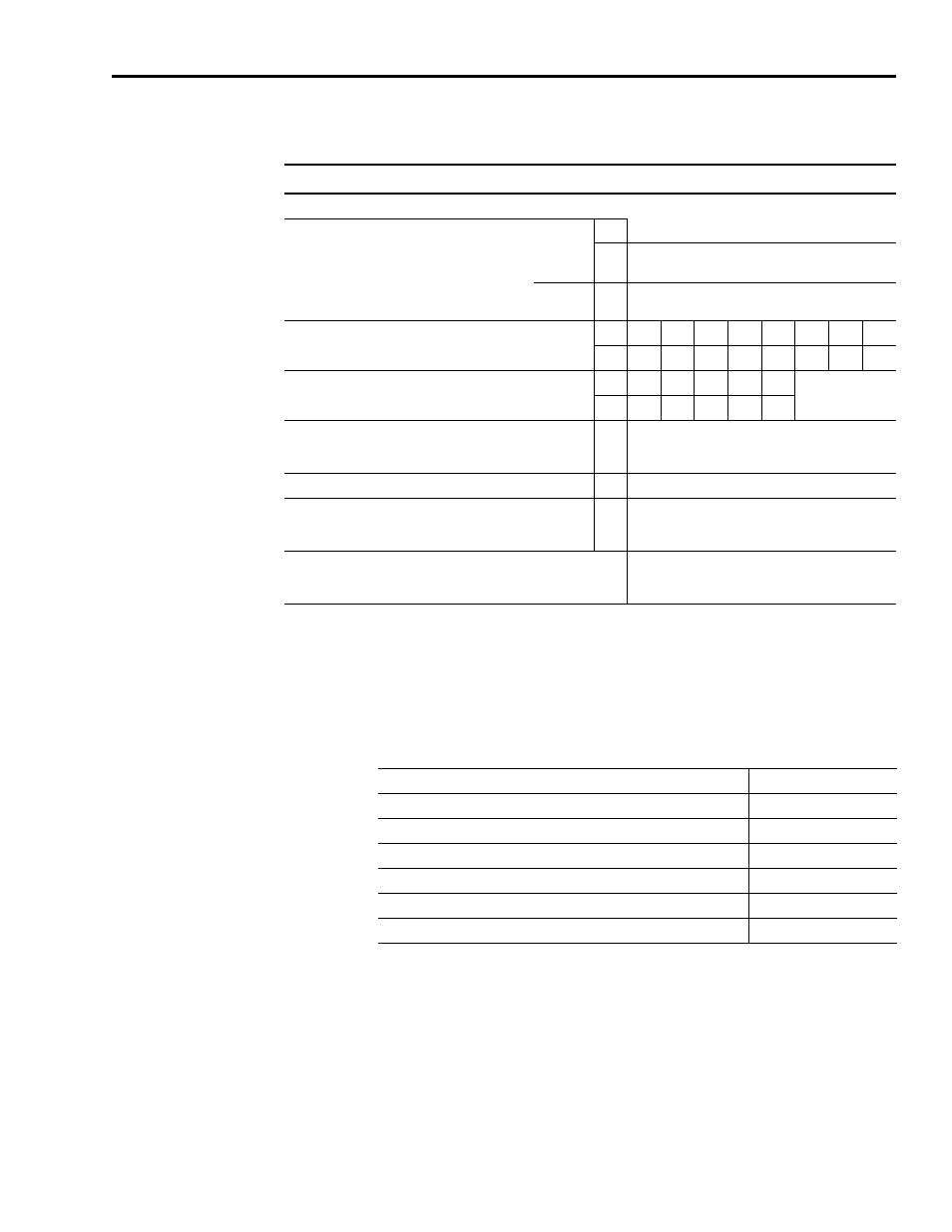
Auxiliary Contact Specifications
Accessory Equipment
The cables provide an interface between the Resistive Brake Module and drive
power terminals. Refer to RBM Wiring Requirements on page 13 for pin,
description, and signal information about the connector kit.
Auxiliary Contacts in Contactor Catalog Number 100-S
1
Current Switching
AC-1Ith
V n/a
at 40° C
(104° F)
A
10
at 60° C
(10°0 F)
A 6
AC-15 at Rated Operating Voltage
V
24
48
120
240
400
500
600
690
A
6
6
6
3
2
1.5
1.2
0,7
DC-13 at Rated Operating g Voltage
V
24
48
125
220
440
A
3
1.5
0.6
0.3
0.2
Short-Circuit Protection
gG Fuse
Type 2 Coordination
A n/a
Rated Impulse Voltage U
imp
kV
n/a
Insulation Voltage
(between control and load circuit DIN,VDE 0106,Part 101
(NAMUR recommendation)
V
Between auxiliary contacts: 250 V
Between load and direct-connected aux. circuits:
690 V
Positively Guided Contacts
Yes,
NO and NC mutually unrestricted, including N.C. in
relation to N.O.
1 Information adapted from the Allen-Bradley Safety Product Catalog (Publication S114-CA001A-EN-P), page 53.
Description
Catalog Number
Kinetix
®
6000 Drive Interface Cable, Resistive Brake - 14 AWG, 66cm
2090-XXNRB-14F0P7
Kinetix 6000 Drive Interface Cable, Resistive Brake - 4, 8, or 10 AWG
2090-XXNRB-aFxxPyy
1, 2
Ultra™ Drive Interface Cable, Resistive Brake - 14 AWG, 132cm
2090-XXNRB-14F1P3
Ultra Drive Interface Cable, Resistive Brake - 6, 8 or 10 AWG
2090-XXNRB-aFxxPyy
1,2
Connector Kit, Resistive Brake, 33A (TB1, TB2, TB3 Connectors)
2090-XNRBM-1
Connector Kit, Resistive Brake,
106A (TB1, TB2, TB3, TB4 Connectors) 2090-XNRBM-2
1 Where a = wire gauge in AWG.
2 Where xx = cable length in full meters, and yy = length in decimeters.