Troubleshooting, 24 vdc status led – Rockwell Automation 2090-XBxxx Resistive Brake Module Installation Instructions User Manual
Page 17
Publication 2090-IN009F-EN-P — November 2004
Resistive Brake Module Installation Instructions
17
Troubleshooting
There are no field replaceable components in an RBM. If problems persist
after attempting to troubleshoot the system, contact your Allen-Bradley
representative for further assistance.
The Status LED is ON when 24V is applied between COIL_A1 and
COIL_A2 (e.g., a Brake Enable signal is received from a drive).
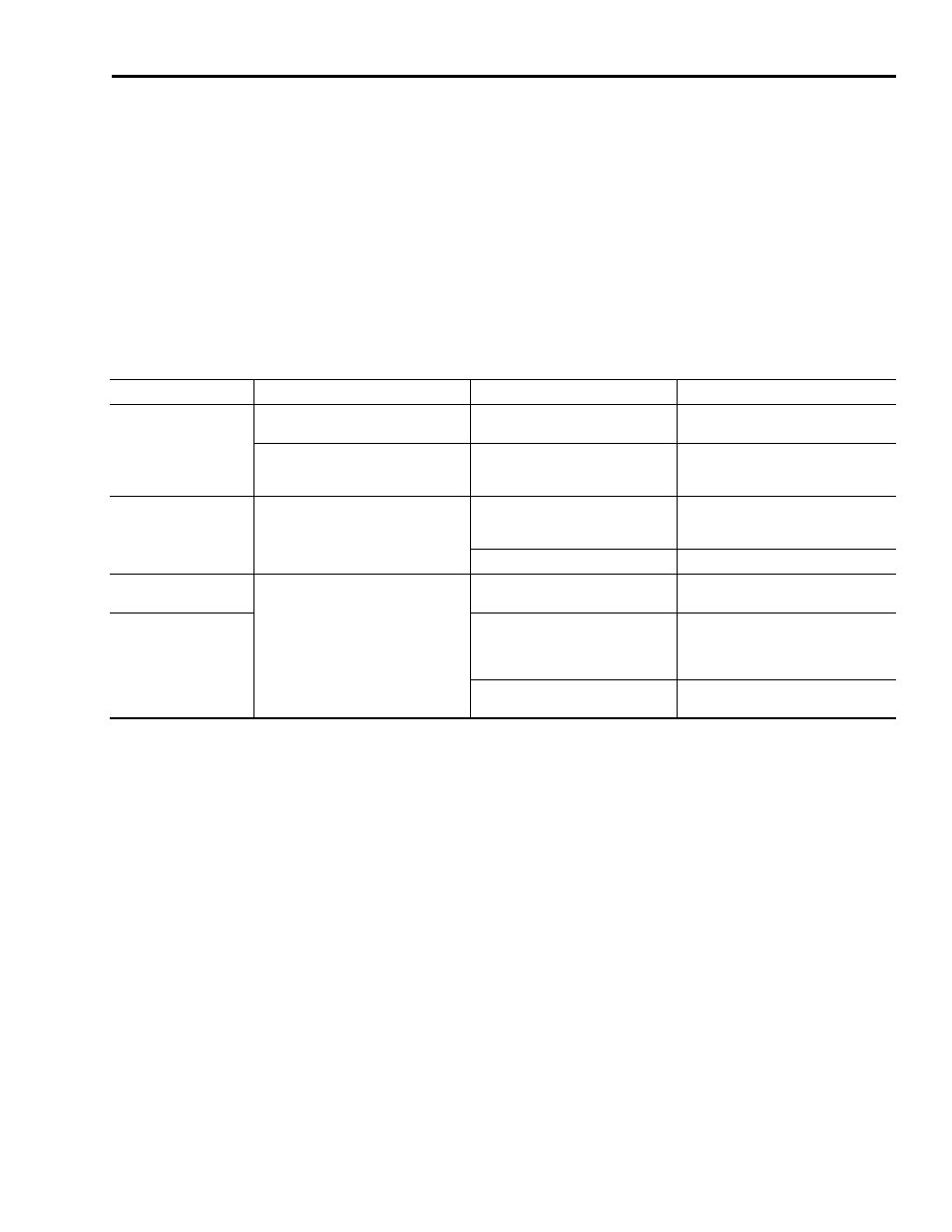
Use the table below for troubleshooting the RBM using the 24 VDC Status
LED.
If 24 VDC Status LED is: RBM Contactor Status is:
Potential Cause is:
Possible Resolution is:
Steady Green
Contactor engaged – direct connection
between drive and motor
No faults or failures
N/A
Contactor disengaged – no connection
between drive and motor
Contactor failure
Verify by monitoring CONSTAT_41/42
status (output is NC)
Contact AB representative
Blinking Green
(audible clicking)
Contactor rapidly engaging/disengaging
Recommended grounding not
followed
• Verify grounding
• Route wires away from noise sources
• Refer to GMC-RM001x-EN-P
Control circuit improperly wired
Verify control wiring and programming
Off
(intended)
Contactor disengaged
(connection open between drive and
motor)
No faults or failures
N/A
Off
(unintended)
+24V not applied between COIL_A1
and COIL_A2
• +24V supply is off
• Verify wiring
• Drive not enabled
• Contact AB representative
T1 (Fault) thermostat open
Duty cycle: exceeded; allow RBM to
cool.