Powerup sequence (dip switch sw-1 off) – Rockwell Automation 2707-L40X_L8X_V40X DTAM Plus Operator Interface Module Installation Instructions User Manual
Page 30
Loading an Application
Chapter 2
2–4
Powerup Sequence (DIP Switch SW-1 OFF)
The following steps show the powerup sequence if DIP switch SW-1 is OFF.
1. The DTAM Plus verifies the system memory checksum, program
checksum, and system RAM. After the test is completed, the result is
displayed with the current DIP switch settings.
Checksum: passed
DIP Switch: 001000
RAM: pass
40K User Memory
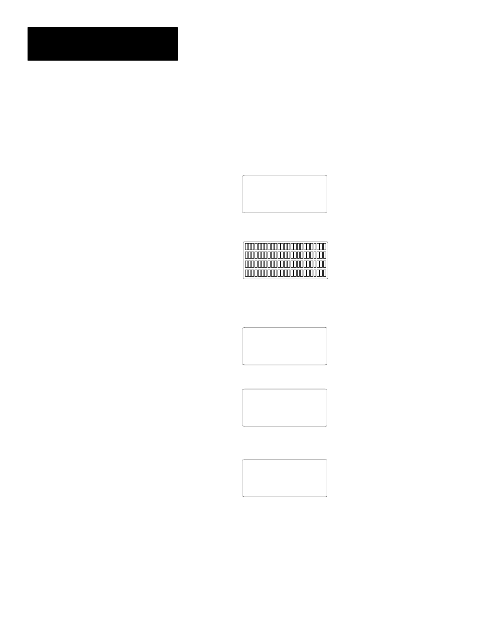
2. The display is tested, every pixel of the display is turned on.
О
ОО
О
ОО
О
О
О
ОО
О
ОО
О
О
ОО
О
О
О
ОО
О
ОО
О
О
О
ОО
О
ОО
О
О
О
О
О
О
ОО
О
О
О
ОО
О
О
О
О
ОО
О
О
О
ОО
О
ОО
О
О
О
О
ОО
О
О
О
О
О
О
ОО
ОО
О
О
О
О
ОО
О
О
О
О
О
О
О
ОО
ОО
О
О
ОО
ОО
О
О
О
О
О
О
ОО
ОО
О
О
ОО
ОО
О
О
О
О
О
О
О
О
О
О
О
О
О
О
ОО
ОО
О
О
ОО
ОО
О
О
О
О
О
О
ОО
ОО
О
О
ОО
ОО
О
О
О
О
О
О
О
О
О
О
О
О
ОО
ОО
О
О
О
О
О
О
ОО
ОО
О
О
О
О
О
О
О
О
ОО
ОО
О
О
О
О
О
О
ОО
ОО
О
О
О
О
О
О
О
О
О
О
О
О
О
О
ОО
ОО
О
О
О
О
О
О
О
О
О
О
О
О
О
О
О
О
О
О
О
О
О
О
О
О
О
О
О
О
ОО
ОО
О
О
О
О
О
О
О
О
О
О
Use this display to verify that all pixels are operational.
3. The operating system firmware release number and protocol is displayed
(PLC5-DF1 or AB DH-485 or Remote I/O).
Allen-Bradley
Operator Interface
DTAM Plus (c) 1996
FRN: 01.20 AB-RIO
4. On 40K versions with a clock, the current time setting is displayed.
DATE: Wed Aug 12 98
TIME: 01:12:47
Diagnostics Complete
5. The first application screen displays. When the DTAM Plus is powered
up for the first time you see:
Bul. 2707 DTAM Plus
No Program Loaded