I/o addressing – Rockwell Automation 6008-SI IBM PC I/O SCNNR 6008-SI User Manual
Page 13
Chapter 2
I/O Scanner Concepts
2-5
Fault dependent group: A group of I/O adapters treated as a single entity
for the purposes of fault detection. If one of the defined group faults all in
the group are in fault.
You assign each adapter an I/O rack number (0 to 7) by setting switches on
the adapter. A rack may be single chassis; or two to four chassis may be
comprised in one rack number; or a single chassis can be addressed as two
racks. It is not necessary to assign rack numbers sequentially: for instance,
you could have a full rack 0, half a rack in rack 3, and a quarter rack in
groups 6–7 of rack 7.
For addressing purposes, each rack is equivalent to a block of 8 I/O groups
in the I/O image table. Groups within a rack are numbered from 0 to 7.
An I/O group is two 16–bit words, one from the output image table and
one from the input image table, with the same address. (Please refer to the
I/O Concepts Manual for more information.) In most applications, only
the input word or only the output word is used in any given I/O group.
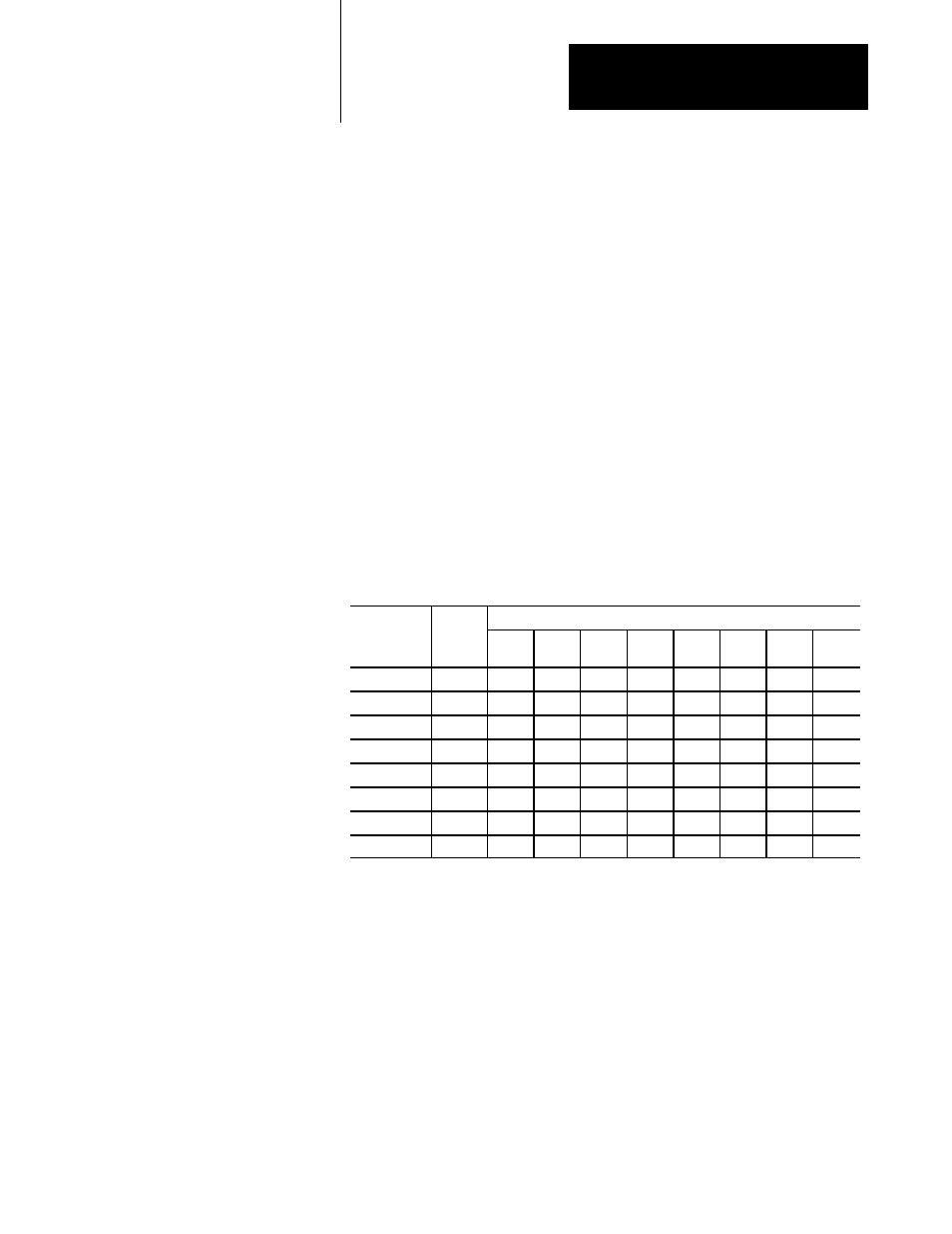
Here is an example layout of the output image table:
Group
word #
(hex)
rack
0
1
2
3
4
5
6
7
00-07
0
xxxx
xxxx
xxxx
xxxx
xxxx
xxxx
xxxx
xxxx
08-0F
1
xxxx
xxxx
xxxx
xxxx
xxxx
xxxx
xxxx
xxxx
10-17
2
xxxx
xxxx
xxxx
xxxx
xxxx
xxxx
xxxx
xxxx
18-1F
3
xxxx
xxxx
xxxx
xxxx
xxxx
xxxx
xxxx
xxxx
20-27
4
xxxx
xxxx
xxxx
xxxx
xxxx
xxxx
xxxx
xxxx
28-2F
5
xxxx
xxxx
xxxx
xxxx
xxxx
xxxx
xxxx
xxxx
30-37
6
xxxx
xxxx
xxxx
xxxx
xxxx
xxxx
xxxx
xxxx
38-3F
7
xxxx
xxxx
xxxx
xxxx
xxxx
xxxx
xxxx
xxxx
The word numbers above can be used as subscripts. (We’ll look closely at
that in chapter 6, Discrete I/O.) Each 16–bit word corresponds to 16
discrete I/O terminal positions, terminal 17 octal (15 decimal) to the
high–order bit and terminal 00 to the low–order bit.
Just as each I/O group has an address, so does each adapter. Adapter
addresses are used in the scan list (see, What the Scanner Does, below).
The adapter address is the address of the first I/O group covered by the
adapter, divided by 2. This is numerically the same as (rack x 4) +
(starting group / 2), where the rack and group are both numbered from 0 to
7 as shown above. If you prefer, you can think of 1/4 racks being
numbered from 0 to 3, and then the adapter address is (rack x 4) +
(quarter).
I/O Addressing