Input module addressing, Appendix b, See appendix b – Rockwell Automation 1769-OF4VI Compact I/O Isolated Analog Modules User Manual
Page 91: Appendix
1
Publication 1769-UM014B-EN-P - May 2010
Appendix
B
Module Addressing and Configuration with
MicroLogix 1500
This appendix examines the analog modules’ addressing scheme and describes
module configuration using RSLogix 500 and MicroLogix 1500 software.
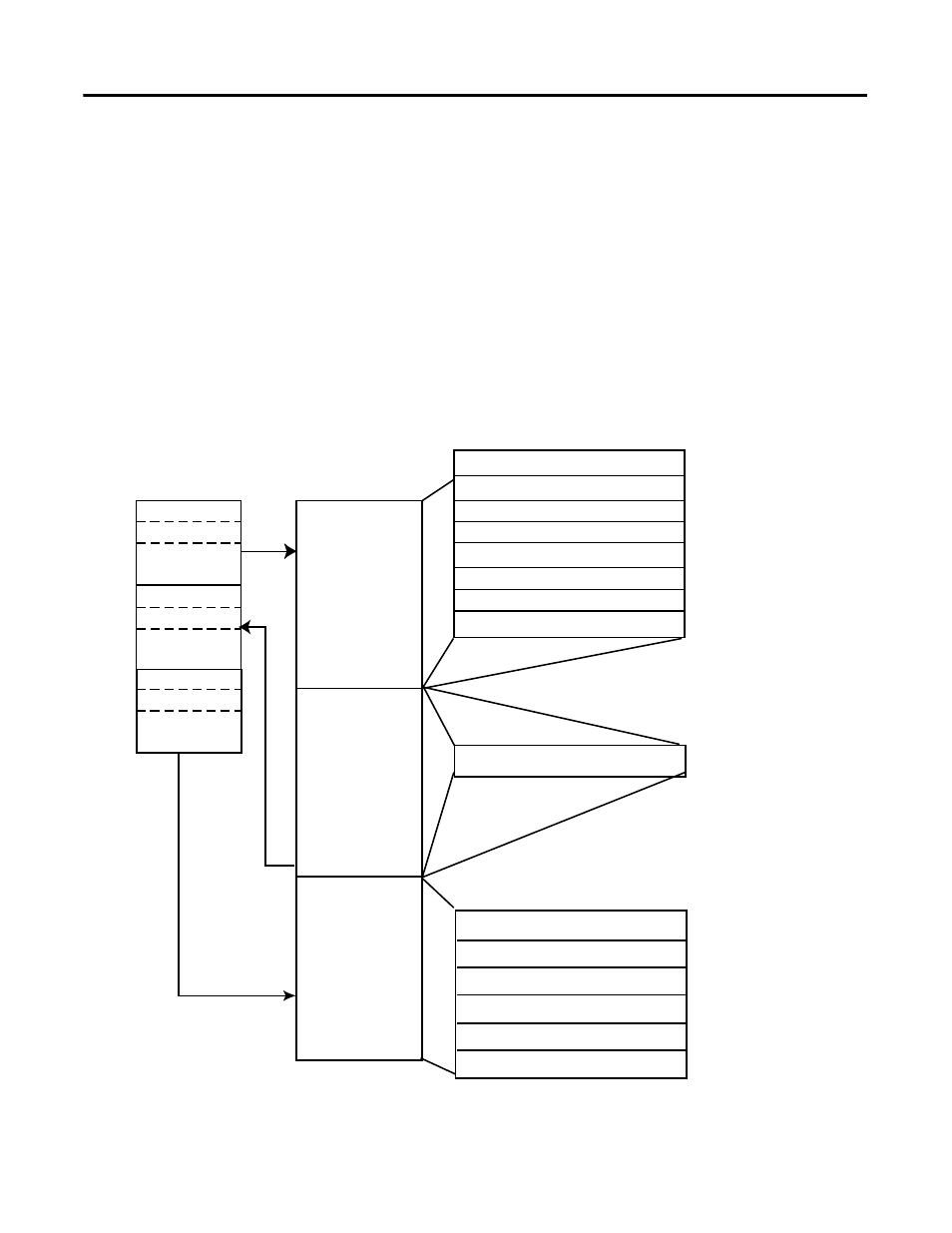
Input Module Addressing
In the following example, the 1769-IF4I module is used.
Detailed information on the input image table can be found in 1769-IF4I
Input Data File on page 3-3.
Figure B.1 1769-IF4I Memory Map
Slot e
Input Image
File
Output Image
File
Configuration
File
Slot e
Slot e
Input Image
7 Words
Output Image
1 Word
Configuration File
26 Words
Memory Map
Bit 15
Bit 0
Channel 3 Configuration Words
Words 20 to 25
Channel 2 Configuration Words
Words 14 to 19
Channel 1 Configuration Words
Words 8 to 13
Channel 0 Configuration Words
Words 2 to 7
Clear Latched Alarm Bits
Word 0
High-/Low-alarm & Over-/Under-range
Word 6
General Status Bits
Word 5
Time Stamp Value Word
Word 4
Channel 3 Data Word
Word 3
Word 2
Channel 2 Data Word
Word 1
Channel 1 Data Word
Channel 0 Data Word
Word 0
Enable Time Stamp
Word 1, bit 15
Real Time Sample Rate
Word 0