Channel configuration, Channel configuration -7 – Rockwell Automation 1769-OF4VI Compact I/O Isolated Analog Modules User Manual
Page 45
Publication 1769-UM014B-EN-P - May 2010
Module Data, Status, and Channel Configuration for the Input Module 3-7
Channel Configuration
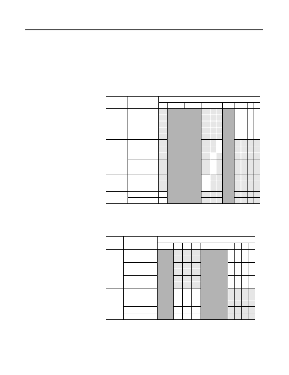
Each channel’s configuration words consist of bit fields, the settings of which
determine how the channel operates. See the table below and the descriptions
that follow for valid configuration settings and their meanings. The default bit
status of the configuration file is all zeros.
Table 3.4 Bit Definitions for Channel Configuration Words
Define
To Select
Make these bit settings
15 14 13 12 11 10 9 8 7…4 3 2 1 0
Input Filter
Selection
60 Hz
0 0 0 0
50 Hz
0 0 0 1
28.5 Hz
0 0 1 0
300 Hz
0 0 1 1
360 Hz
0 1 0 0
Enable
Interrupt
Enable
(1)
(1)
CompactLogix L43 controllers will be able to support these interrupts.
1
Disable
0
Enable
Process
Alarm
Latch
Enable
1
Disable
0
Enable
Process
Alarms
Enable
1
Disable
0
Enable
Channel
Enable
1
Disable
0
Table 3.5 Bit Definitions for Input Range and Input Data
Define Indicate this
These bit settings
15…11 10 9
8
7…4
3 2 1 0
Input
Range
Select
-10…+10V dc
0 0 0 0
0…5V dc
0 0 0 1
0…10V dc
0 0 1 0
4…20 mA
0 0 1 1
1…5V dc
0 1 0 0
0…20 mA
0 1 0 1
Input
Data
Format
Select
Raw/Proportional
Counts
0
0
0
Engineering Units
0
0
1
Scaled for PID
0
1
0
Percent Range
0
1
1