1769-of4ci and -of4vi configuration data file, 1769-of4ci and -of4vi configuration data file -7 – Rockwell Automation 1769-OF4VI Compact I/O Isolated Analog Modules User Manual
Page 59
Publication 1769-UM014B-EN-P - May 2010
Module Data, Status, and Channel Configuration for the Output Modules 4-7
1769-OF4CI and -OF4VI
Configuration Data File
The configuration file lets you determine how each individual output channel
will operate. Parameters such as the output type/range and data format are set
up using this file. The configuration data file is writable and readable. The
default value for the configuration data file is all zeros. The structure of the
channel configuration file is explained below.
The configuration file is typically modified using the programming software
configuration screen.
For information on configuring the module using MicroLogix 1500 and
RSLogix 500 software, see Appendix B; for CompactLogix and RSLogix 5000
software, see Appendix C; for 1769-ADN DeviceNet adapter and RSNetWorx
software, see Appendix D.
The configuration file can also be modified through the control program, if
supported by the controller.
The structure and bit settings are shown in 1769-OF4CI and -OF4VI Channel
Configuration on page 4-8.
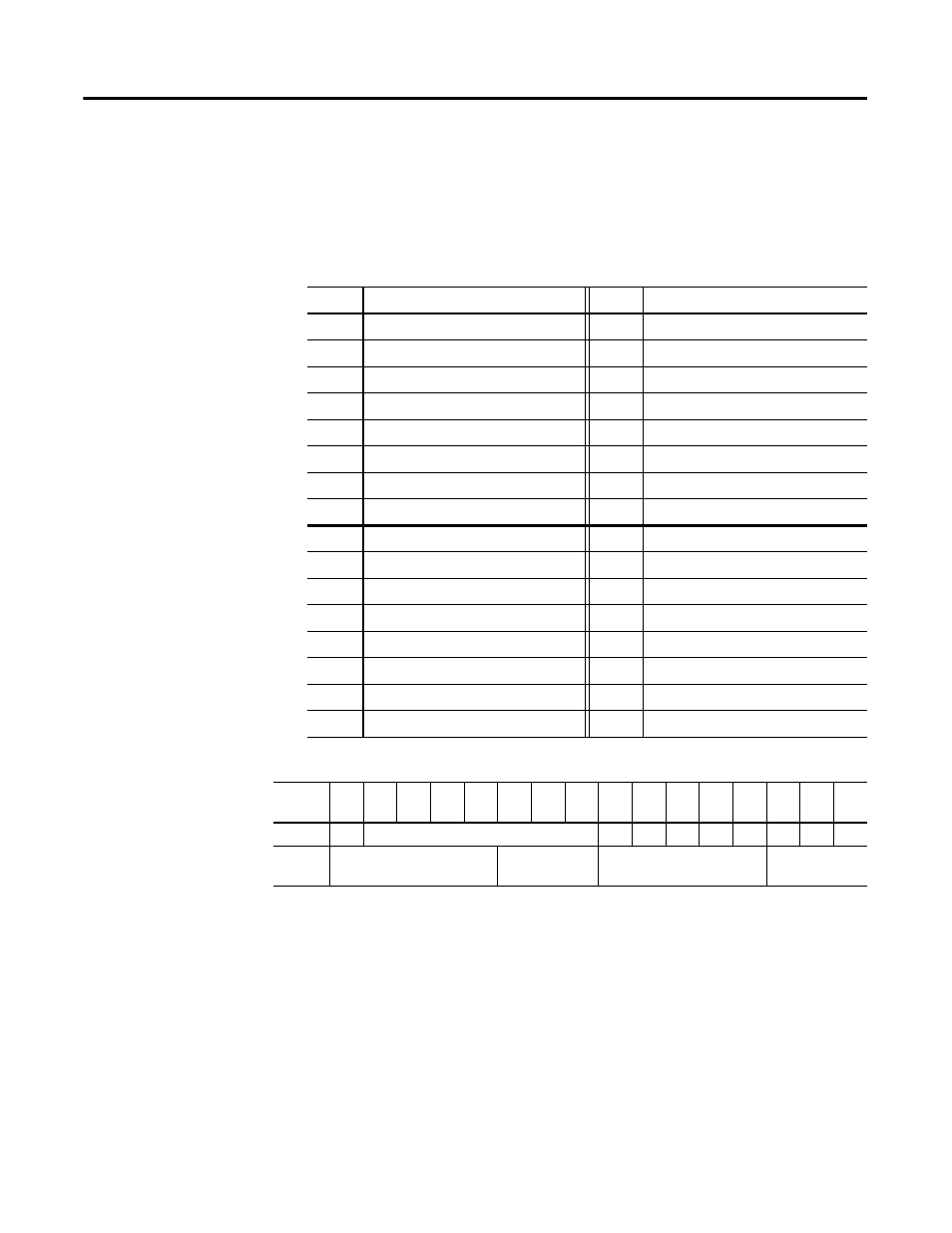
Table 4.4 1769-OF4CI and -OF4VI Configuration Data File
Word
Description
Word
Description
0
Channel 0 Configuration Word 0
16
Channel 2 Configuration Word 0
1
Channel 0 Configuration Word 1
17
Channel 2 Configuration Word 1
2
Channel 0 Fault Value Word
18
Channel 2 Fault Value Word
3
Channel 0 Program Idle Mode Word
19
Channel 2 Program Idle Mode Word
4
Channel 0 Low Clamp
20
Channel 2 Low Clamp
5
Channel 0 High Clamp
21
Channel 2 High Clamp
6
Channel 0 Ramp Rate
22
Channel 2 Ramp Rate
7
Channel 0 Spare
23
Channel 2 Spare
8
Channel 1 Configuration Word 0
24
Channel 3 Configuration Word 0
9
Channel 1 Configuration Word 1
25
Channel 3 Configuration Word 1
10
Channel 1 Fault Value Word
26
Channel 3 Fault Value Word
11
Channel 1 Program Idle Mode Word
27
Channel 3 Program Idle Mode Word
12
Channel 1 Low Clamp
28
Channel 3 Low Clamp
13
Channel 1 High Clamp
29
Channel 3 High Clamp
14
Channel 1 Ramp Rate
30
Channel 3 Ramp Rate
15
Channel 1 Spare
31
Channel 3 Spare
Table 4.5 1769-OF4CI and -OF4VI Configuration Words 0 and 1 Bit Descriptions
Word/
Bit
15
14
13
12
11
10
9
8
7
6
5
4
3
2
1
0
Word 0
E
Reserved
SIU SIO LA
ER FM PM HI PFE
Word 1
Reserved
Output Data
Format Select
Reserved
Output
Type/Range