Rockwell Automation 1769-OF4VI Compact I/O Isolated Analog Modules User Manual
Page 27
Publication 1769-UM014B-EN-P - May 2010
Installation and Wiring 2-11
1769-IF4I Input Module Guidelines
If multiple power supplies are used with analog inputs, the power supply
commons must be kept at potentials that do not result in the module’s
working voltage rating being exceeded.
The 1769-IF4I module does not provide loop power for analog inputs.
Use power supplies that match the input transmitter specifications.
Differential analog inputs are more immune to noise than single-ended
analog inputs.
Voltages on Ch+, Ch-, and Ch_IRtn for a single, isolated channel of the
1769-IF4I module must not exceed the module’s maximum overload
levels.
1769-IF4I channels used as current inputs require a jumper to be placed
between a channel’s CH_IRtn and Ch- terminals.
1769-OF4CI and -OF4VI Output Modules Guidelines
Voltage outputs (Vout 0+ to Vout 3+ for 1769-OF4VI) of the output
module are referenced to each channel’s Vout- terminal (channels are
isolated from each other). Load resistance for a voltage output channel
must be equal to or greater than 2 k.
Current outputs (Iout 0+ to Iout 3+ for 1769-OF4CI) of the output
module source current that returns to each channel’s Iout- terminal
(channels are isolated from each other). Load resistance for a current
output channel must remain between 0 and 500 .
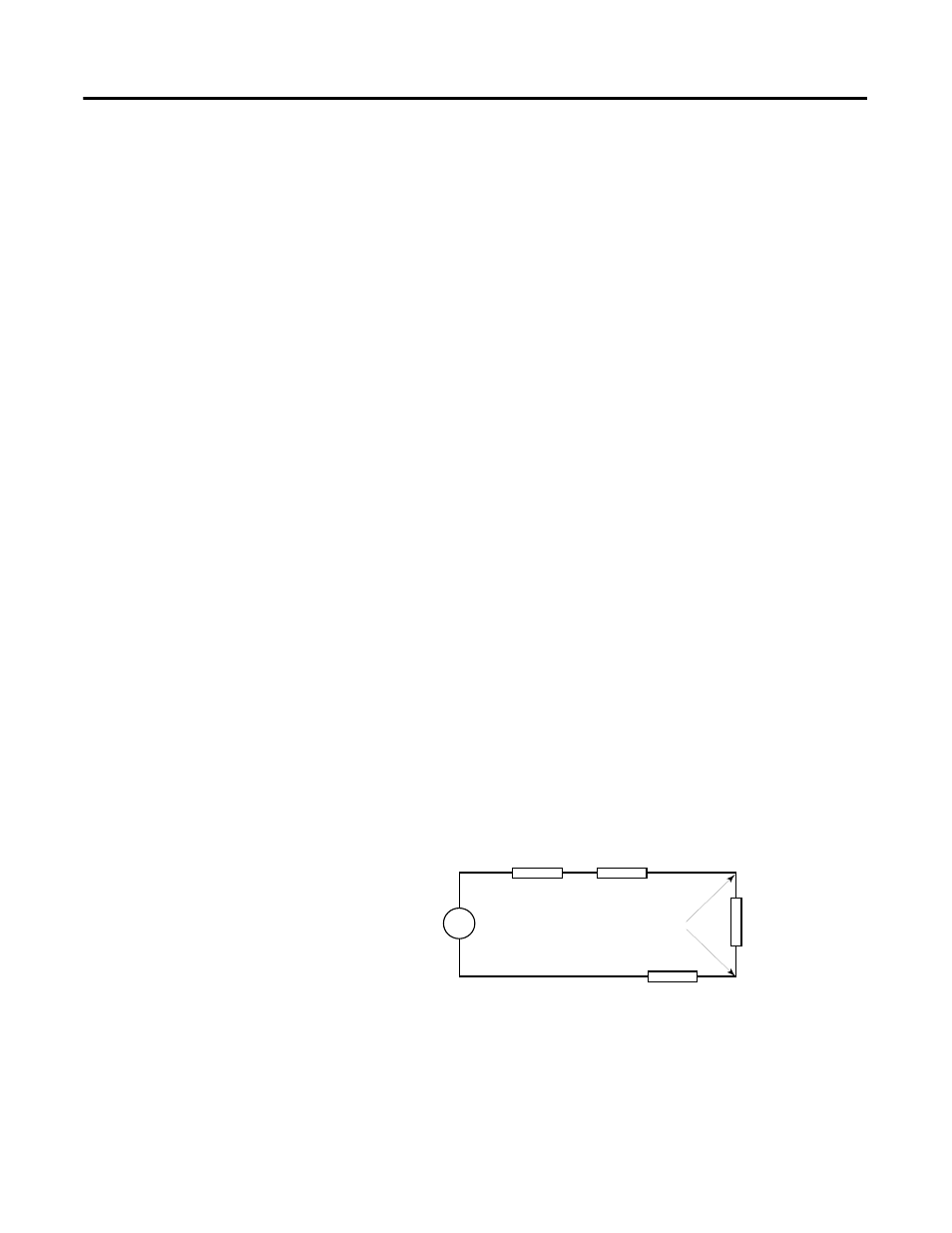
Effect of Transducer/Sensor and Cable Length Impedance on Voltage Input
Accuracy
For voltage inputs, the length of the cable used between the transducer/sensor
and the 1769-IF4I module can affect the accuracy of the data provided by the
module.
Figure 2.4 Voltage Input Accuracy
V in
Vs
Ri
Rc
Rc
Rs
+
-