1769-of4ci and -of4vi channel configuration, 1769-of4ci and -of4vi channel configuration -8 – Rockwell Automation 1769-OF4VI Compact I/O Isolated Analog Modules User Manual
Page 60
Publication 1769-UM014B-EN-P - May 2010
4-8 Module Data, Status, and Channel Configuration for the Output Modules
1769-OF4CI and -OF4VI Channel Configuration
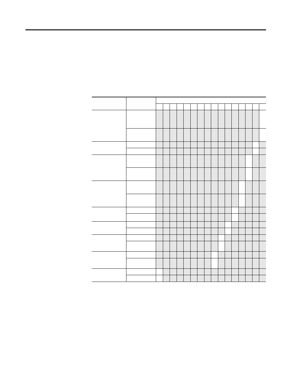
The first two words of each eight word group in the configuration file allow
you to change the parameters of each channel independently. For example,
words 8 and 9 correspond to channel 1 while words 24 and 25 correspond to
channel 3.
Table 4.6 1769-OF4CI and -OF4VI Channel Configuration Word 0
(1)
Define
Indicate
Bit Settings
15 14 13 12 11 10 9 8 7 6 5 4 3 2 1 0
Program (Idle) to
Fault Enable
Program (Idle)
Mode Data
Applied
(2)
0
Fault Mode
Data Applied
1
Hold for
Initialization
Disabled
0
Enabled
1
Program (Idle)
Mode
Hold Last
State
0
User-Defined
Value
1
Fault Mode
Hold Last
State
0
User-Defined
Fault Value
1
Enable Ramping
Disabled
0
1
Enable Clamp/
Alarm Latching
Disabled
0
Enabled
1
Enable High
Clamp/ Alarm
Interrupt
Disabled
0
1
Enable Low
Clamp/ Alarm
Interrupt
Disabled
0
1
Enable Channel
Disabled
0
Enabled
1
(1)
Refer to the 1769-OF4CI and -OF4VI Output Channel Configuration Word 1 table.
(2)
Hold Last State and User Defined Fault functionality is only supported when the analog module is used in a DeviceNet
application via the 1769-ADN adapter No local configuration, that is, a MicroLogix or CompactLogix system, supports this
functionality. Refer to your controller manual for details.