Field device configuration – Rockwell Automation 1788-CN2FFR EtherNet/IP and ControlNet to FOUNDATION Fieldbus Linking Device User Manual
Page 34
32
Rockwell Automation Publication 1788-UM057B-EN-P - September 2014
Chapter 2
Set Up in the Studio 5000 Logix Designer Application
Field Device Configuration
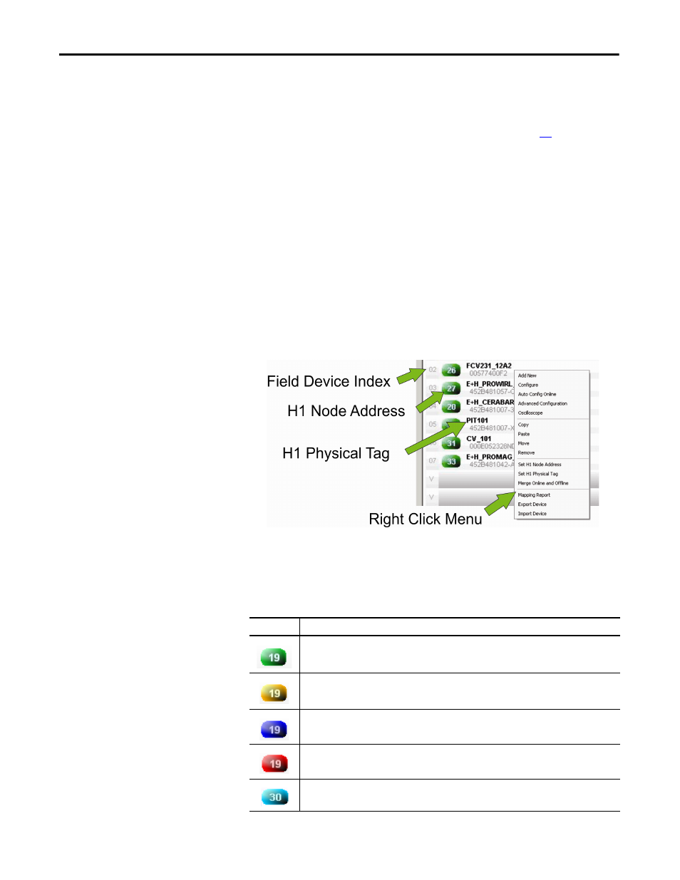
The overview page on the configuration tab displays the field device live list with
colored icons that depict the status of each field device (see page
). If the Studio
5000 Logix Designer application is online with the 1788-CN2FFR/1788-
EN2FFR link master correctly configured, the attached field devices appear in
the live list.
The field device index (00
→15) provides a unique index for each of the 16 field
devices that can be connected to the linking device. This index corresponds with
the index in the linking device data structure that is located in the controller tags.
The H1 node address and physical tag are also displayed together with the device
ID and serial number of the field device.
A right-click menu in the overview page displays functions for addition,
configuration, and diagnostics of field devices.
Figure 3 - Overview Page on the Configuration Tab
Field Device Status
The icon color indicates the status of the field device.
Table 2 - Field Device Status Icons
Icon
Description
Green – Field device is online, allocated to a field device index and configured, producing process
variables.
Yellow – Field device is online, not allocated to a field device index and not configured.
Blue – Field device is online, allocated but not configured or producing process variables.
Red – Field device is not online.
Light blue – Field device identification mismatch (occurs when the field device identity [ident] that is
downloaded to the linking device is different than the actual field device).