Linking device configuration using the aop – Rockwell Automation 1788-CN2FFR EtherNet/IP and ControlNet to FOUNDATION Fieldbus Linking Device User Manual
Page 28
26
Rockwell Automation Publication 1788-UM057B-EN-P - September 2014
Chapter 2
Set Up in the Studio 5000 Logix Designer Application
Linking Device Configuration
Using the AOP
Once the linking device has been added to the config tree, you can access the
property settings. Right-click the linking device and select Properties. Then click
the Configuration tab as shown in
Figure 1
.
Once the linking device is connected to the controller, you can see the linking
device in the Configuration tab.
•
Master green in the config tree = linking device is online
•
Master gray in the config tree = linking device is offline
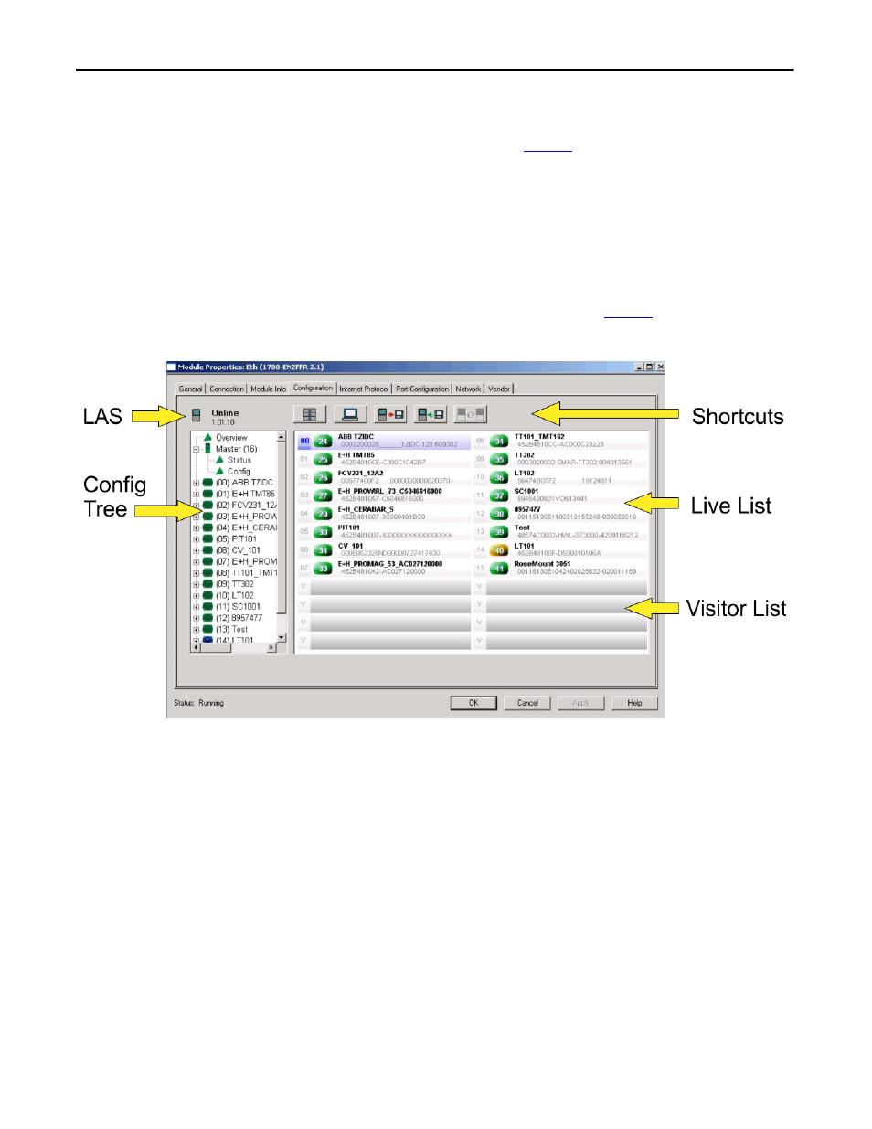
The layout of the Configuration tab is shown in
Figure 1
.
Figure 1 - Module Properties Configuration Tab
Live List
Once a field device is found and has an address between 16 (0x10) and
247 (0xF7), the device appears in the live list. You can configure this device.
Visitor List
Once a field device is found and has an address above 247 (0xF7), the device
appears in the visitor list. You cannot configure this device until an address
between 16 (0x10) and 247 (0xF7) is given to the field device. See Live List.