Rockwell Automation 1770-HT8 SMART TRANSMITTER User Manual
Page 92
Chapter 4
C
Communicating with the Smart
Transmitter Interface
4-27
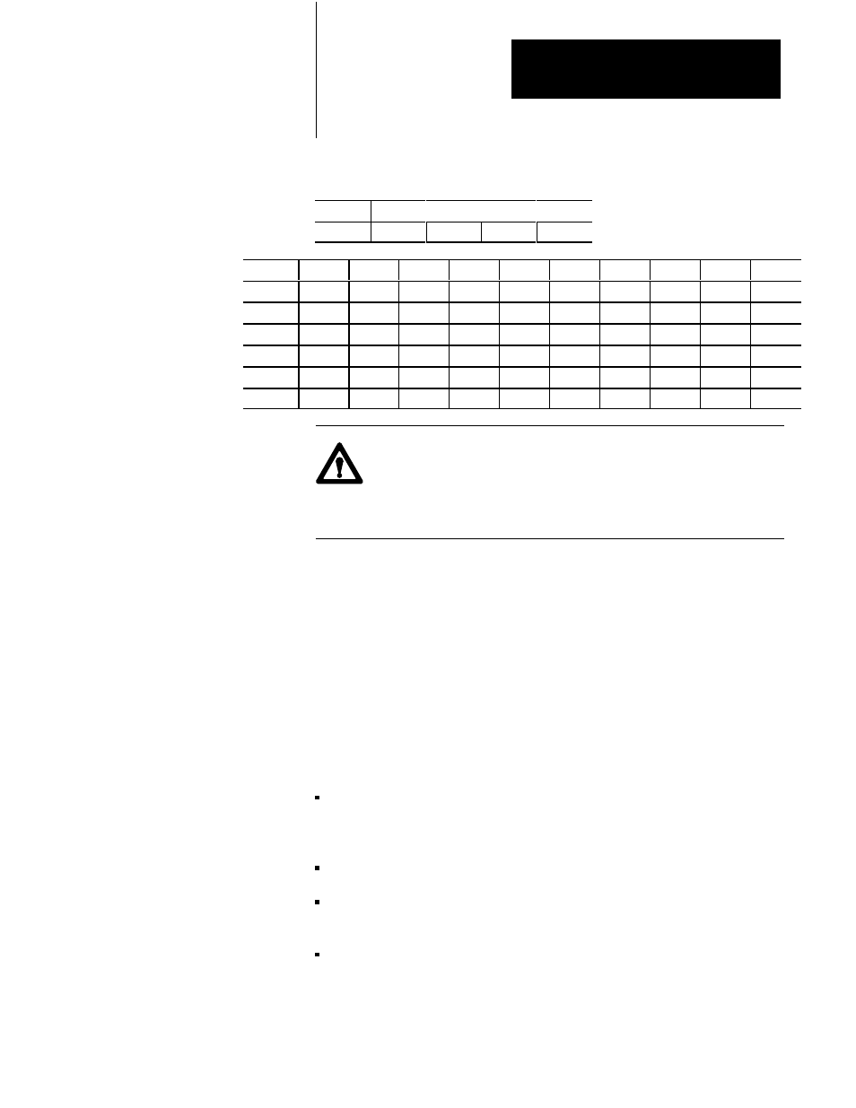
Table 4.K
PLCĆ5 Data Tables for Example Program
Address
15
Data
0
B3:0
0000
0000
0000
0000
Address
0
1
2
3
4
5
6
7
8
9
D9:00
0110
0000
8002
0000
0000
0000
0000
0000
0000
0000
D9:10
0110
0000
8082
0000
0000
0001
0000
0000
0000
0000
D9:20
0000
0000
0000
0000
0000
0000
0000
0000
0000
0000
D9:30
0000
0000
0000
0000
0000
0000
0000
0000
0000
0000
D9:40
0000
0000
0000
0000
0000
0000
0000
0000
0000
0000
D9:50
0000
0000
0000
0000
0000
0000
0000
0000
0000
0000
ATTENTION: The BTR command must have a data file length
between 1 and 63. Zero is reserved for hosts on the Data
Highway Plus which use the pass through functionality of the
programmable controller.
This program assumes that the Smart Transmitter Interface is configured
for rack 1, group 2 and the HART field device is connected to channel 2 of
the Terminal Block. HART command #0 is first sent to a field device to
obtain its long frame address. Then the program continually sends HART
command #1 to the field device and obtains its response. If the Smart
Transmitter Interface returns a non-zero error code in the Smart
Transmitter Interface Error Code, the PLC-5 program sends HART
command #0 and repeats the above cycle. You can also force the
programmable controller to resend HART command #0 by clearing bit
B3:0.
The rungs in Figure 4.10 perform the following functions:
Rung 0: Sets up the BTW data for a short frame HART command #0
and clears B3:0 to indicate that the long frame address must be
initialized.
Rung 1: Performs the BTW if no previous BTW or BTR is active.
Rung 2: Performs the BTR if no previous BTW or BTR is active and if
the BTW is completed.
Rung 3: Moves the Smart Transmitter Interface Error Code received
from the Smart Transmitter Interface to D9:30 and sets B3:3 to indicate
that the data received in the BTR is valid.