Rockwell Automation 1770-HT8 SMART TRANSMITTER User Manual
Page 50
Installing the Smart Transmitter Interface
Products
Chapter 2
2-25
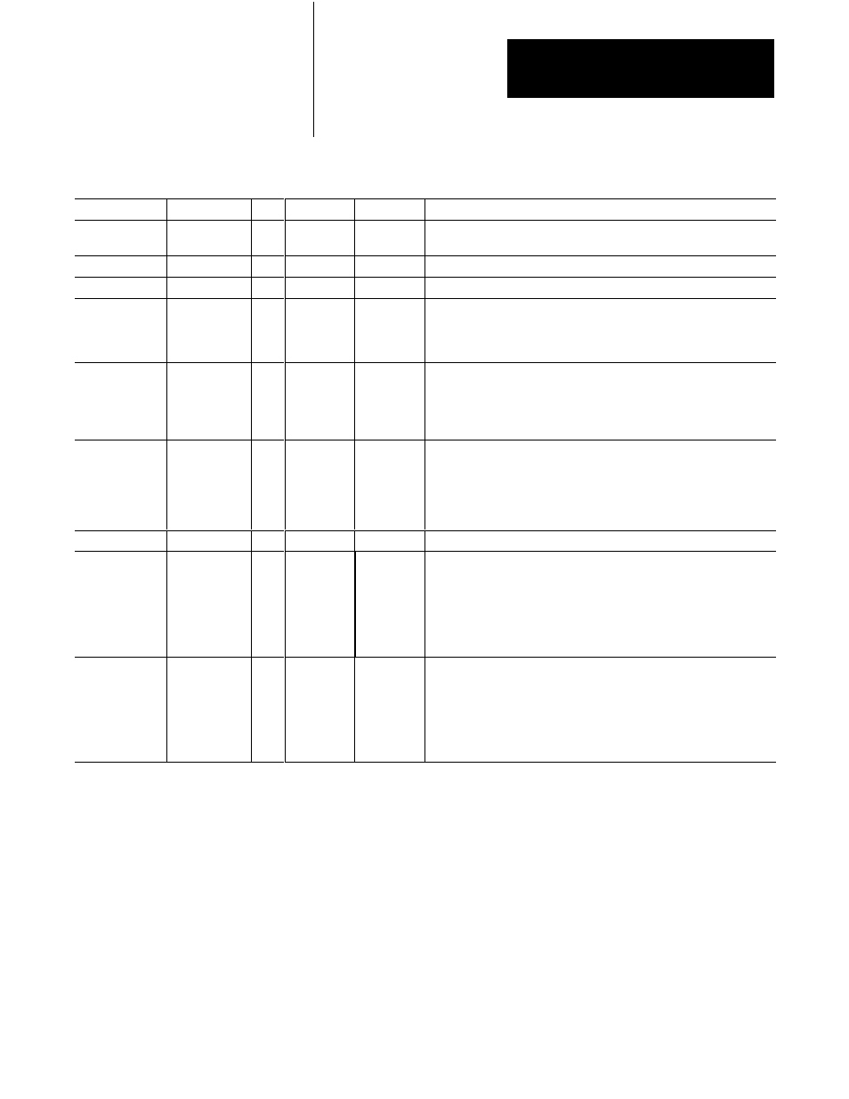
Table 2.A
RSĆ232C Connector Pinouts
Signal
Abbreviation
I/O
Direction
Pin Number Meaning
БББББ
Б
БББ
Б
Chassis Ground
БББББ
Б
БББ
Б
N/A
ББББ
Б
ББ
Б
-
ББББ
Б
ББ
Б
1
ББББББББББББББББББ
Б
ББББББББББББББББ
Б
The cable shield must be connected to chassis ground at one end only.
It is recommended that you do this at the Communications Controller end.
БББББ
Б
БББ
Б
Transmit Data
БББББ
Б
БББ
Б
TXD
O
ББББ
Б
ББ
Б
Output
ББББ
Б
ББ
Б
2
ББББББББББББББББББ
Б
ББББББББББББББББ
Б
RSĆ232C serialized data output from the Communications Controller.
БББББ
Б
БББ
Б
Receive Data
БББББ
Б
БББ
Б
RXD
I
ББББ
Б
ББ
Б
Input
ББББ
Б
ББ
Б
3
ББББББББББББББББББ
Б
ББББББББББББББББ
Б
RSĆ232C serialized data input to the Communications Controller.
БББББ
Б
БББ
Б
Б
БББ
Б
Б
БББ
Б
Request to Send
БББББ
Б
БББ
Б
Б
БББ
Б
Б
БББ
Б
RTS
O
ББББ
Б
ББ
Б
Б
ББ
Б
Б
ББ
Б
Output
ББББ
Б
ББ
Б
Б
ББ
Б
Б
ББ
Б
4
ББББББББББББББББББ
Б
ББББББББББББББББ
Б
Б
ББББББББББББББББ
Б
Б
ББББББББББББББББ
Б
A request from the Communications Controller to the modem to prepare to
transmit. With full duplex protocol, RTS is always asserted. With half
duplex protocol, it is turned on when the Communications Controller has
permission to transmit, otherwise it is off.
БББББ
Б
БББ
Б
Б
БББ
Б
Б
БББ
Б
БББББ
Clear to Send
БББББ
Б
БББ
Б
Б
БББ
Б
Б
БББ
Б
БББББ
CTS
I
ББББ
Б
ББ
Б
Б
ББ
Б
Б
ББ
Б
ББББ
Input
ББББ
Б
ББ
Б
Б
ББ
Б
Б
ББ
Б
ББББ
5
ББББББББББББББББББ
Б
ББББББББББББББББ
Б
Б
ББББББББББББББББ
Б
Б
ББББББББББББББББ
Б
ББББББББББББББББББ
A signal from the modem to the Communications Controller that indicates
the carrier is stable and the modem is ready to transmit. The
Communications Controller will not transmit until CTS is on. If CTS is
turned off during transmission, the Communications Controller will stop
transmitting until CTS is restored.
БББББ
Б
БББ
Б
Б
БББ
Б
Б
БББ
Б
БББББ
Data Set Ready
БББББ
Б
БББ
Б
Б
БББ
Б
Б
БББ
Б
БББББ
DSR
I
ББББ
Б
ББ
Б
Б
ББ
Б
Б
ББ
Б
ББББ
Input
ББББ
Б
ББ
Б
Б
ББ
Б
Б
ББ
Б
ББББ
6
ББББББББББББББББББ
Б
ББББББББББББББББ
Б
Б
ББББББББББББББББ
Б
Б
ББББББББББББББББ
Б
ББББББББББББББББББ
A signal from the modem to the Communications Controller that indicates
the phone is off-hook. It is the modem's answer to DTR. The
Communications Controller will not transmit or receive unless DSR is on. If
the modem does not control DSR properly, DSR must be jumpered to a
high signal at the Communications Controller. (It can be jumpered to
DTR.)
БББББ
БББББ
Signal Ground
БББББ
БББББ
GND
N/A
ББББ
ББББ
-
ББББ
ББББ
7
ББББББББББББББББББ
ББББББББББББББББББ
Signal ground - a reference point for the data signals.
БББББ
Б
БББ
Б
Б
БББ
Б
Б
БББ
Б
Б
БББ
Б
БББББ
Data Carrier
Detect
БББББ
Б
БББ
Б
Б
БББ
Б
Б
БББ
Б
Б
БББ
Б
БББББ
DCD
I
ББББ
Б
ББ
Б
Б
ББ
Б
Б
ББ
Б
Б
ББ
Б
ББББ
Input
ББББ
Б
ББ
Б
Б
ББ
Б
Б
ББ
Б
Б
ББ
Б
ББББ
8
ББББББББББББББББББ
Б
ББББББББББББББББ
Б
Б
ББББББББББББББББ
Б
Б
ББББББББББББББББ
Б
Б
ББББББББББББББББ
Б
ББББББББББББББББББ
A signal from the modem to the Communications Controller to indicate
that the carrier from another modem is being sensed on the phone line. It
will not be asserted unless the phone is off-hook. Data will not be
received by the Communications Controller unless DCD is on. With full
duplex protocol, the Communications Controller will not transmit unless
DCD is on. If the modem does not control DCD properly, DCD must be
jumpered to DTR at the module.
БББББ
Б
БББ
Б
Б
БББ
Б
Б
БББ
Б
Б
БББ
Б
БББББ
Data Terminal
Ready
БББББ
Б
БББ
Б
Б
БББ
Б
Б
БББ
Б
Б
БББ
Б
БББББ
DTR
O
ББББ
Б
ББ
Б
Б
ББ
Б
Б
ББ
Б
Б
ББ
Б
ББББ
Output
ББББ
Б
ББ
Б
Б
ББ
Б
Б
ББ
Б
Б
ББ
Б
ББББ
20
ББББББББББББББББББ
Б
ББББББББББББББББ
Б
Б
ББББББББББББББББ
Б
Б
ББББББББББББББББ
Б
Б
ББББББББББББББББ
Б
ББББББББББББББББББ
A signal from the Communications Controller to the modem to connect to
the phone line (i.e., "pick up the phone"). The Communications Controller
will assert DTR all the time except during the phone hang-up sequence.
Modems built to North American standards will not respond to DTR until
the phone rings. The Communications Controller will not work correctly
with modems which always pick up the phone upon receiving DTR,
whether the phone is ringing or not.
The connector you use at the computer end of the cable depends on
whether or not your application makes use of handshake signals, whether
or not you are connecting to a 9 pin serial port for an IBM AT, and whether
or not your computer uses standard IBM pinouts. The following diagrams,
Figure 2.21 through Figure 2.26, are for IBM computers with either 9 or 25
pin connectors. If your computer has a different pinout, construct a cable
using the appropriate signal names for your computer.
If you are not using handshake signals, use the three wire connections
shown in Figure 2.21 or Figure 2.22.