2ć19 – Rockwell Automation 1770-HT8 SMART TRANSMITTER User Manual
Page 44
Installing the Smart Transmitter Interface
Products
Chapter 2
2-19
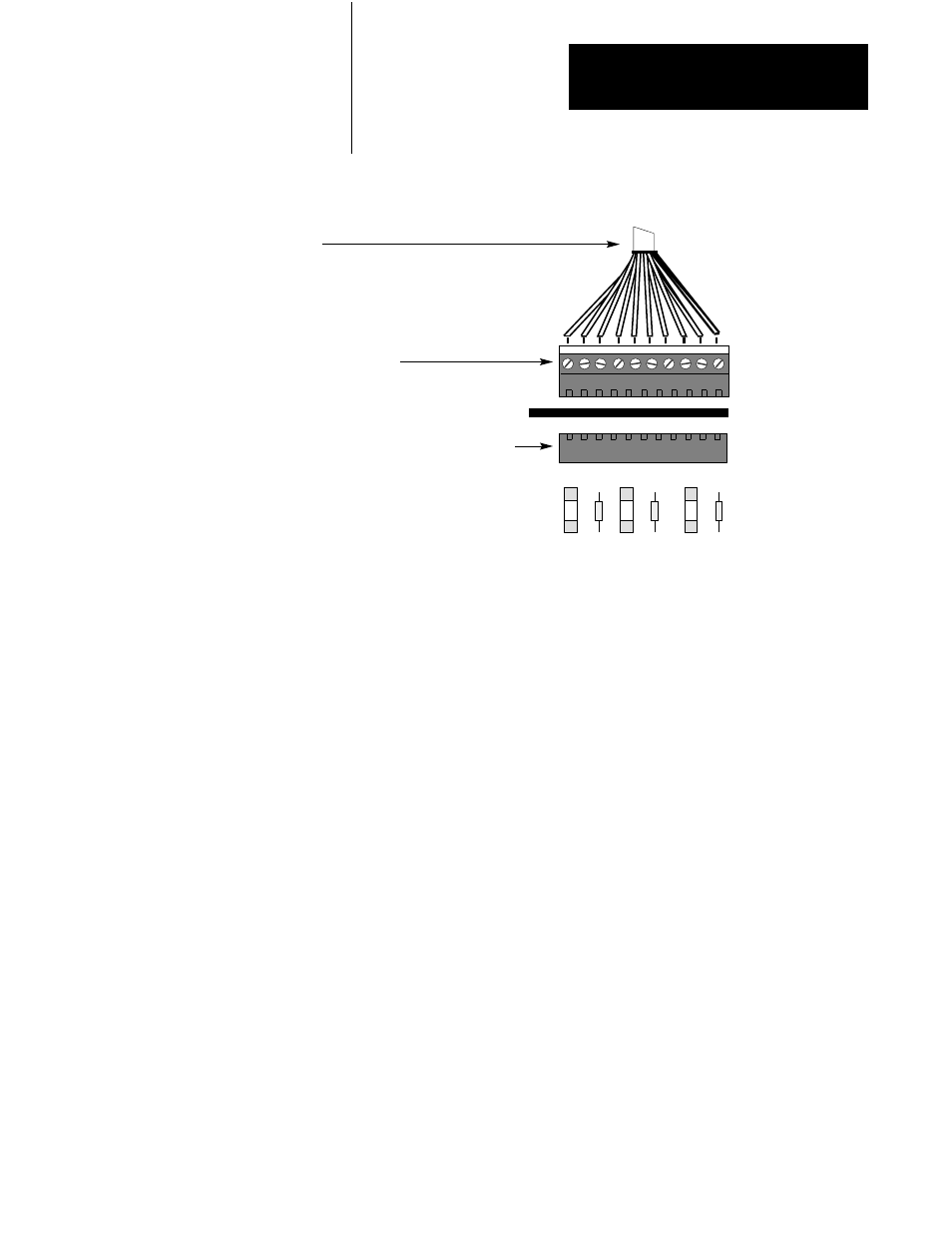
Figure 2.17
Grounding Analog I/O
90045
1 2 3 4 5 6 7 8 RTN SH
To Analog I/O
10 position COMBICON plug
10 position COMBICON connector on Terminal Block
The Communications Controller requires an external 24 VDC power
supply with
" 1% voltage regulation. The power supply must provide the
Communications Controller with 200 mA of current. It must also provide
an additional 100 mA of current for each Terminal Block that is connected
to the Communications Controller. For example, the setup in Figure 2.3
requires a 24 VDC power supply that can provide at least 500 mA. Please
refer to Appendix C if your cable length requirement exceeds those shown
in Figure 2.3 to Figure 2.5. For recommended power supplies see
Appendix C, Table C.A.
Fuses for the Communications Controller
Overload protection for external power is provided by a 1 Amp
user-replaceable fuse located immediately below the power connector on
the Communications Controller. The fuse is UL 198G and CSA 22.2, No.
59 rated, 5mm x 20mm, 250V fast acting.
Supplying Power to the
Communications Controller
and Terminal Blocks