4ć17 – Rockwell Automation 1770-HT8 SMART TRANSMITTER User Manual
Page 82
Chapter 4
C
Communicating with the Smart
Transmitter Interface
4-17
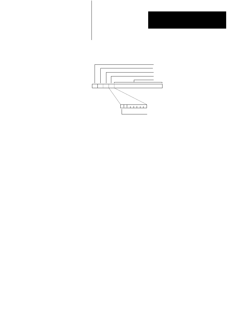
Figure 4.9
Smart Transmitter Interface Packets Ć Smart Transmitter Interface to Programmable
Controller or Host Computer
90076
Smart Transmitter Interface Command
Smart Transmitter Interface Channel Number (00 - 1F, FF)
Smart Transmitter Interface Error Code
Smart Transmitter Interface Status
Smart Transmitter Interface Data
Cold Start Bit
1 Communications Controller powered down or reset
0 0 0 0 0 0 0
MSB
Smart Transmitter Interface Channel
In this field, the Smart Transmitter Interface echoes the channel number
associated with the response it is sending.
Smart Transmitter Interface Error Code
In this field, the Smart Transmitter Interface places the error codes it is
returning, as described in Table 4.F.
Smart Transmitter Interface Status
The most significant bit in this field is used as a cold start bit. On powerup
the Smart Transmitter Interface sets it (to 1). It remains set until the Smart
Transmitter Interface receives an Enable Poll and Response mode
command (hexadecimal 01) or an Enable Burst Monitor mode command
(hexadecimal 02). All other bits are set to 0.
When this bit changes state from 0 to 1, it indicates to the host processor
that power was cycled to the Smart Transmitter Interface leaving it in Poll
and Response mode with an empty Burst Data Table, the number of
preambles for all channels set to 10 and the number of retries for all
channels set to 3.
Upon detecting this condition, you should reinitialize the Smart
Transmitter Interface as required for your application.