Determining module update time – Rockwell Automation 1769-IR6 Compact I/O 1769-IR6 RTD/Resistance Input Module User Manual
Page 72
72
Rockwell Automation Publication 1769-UM005B-EN-P - March 2012
Chapter 4 Module Data, Status, and Channel Configuration
Determining Module
Update Time
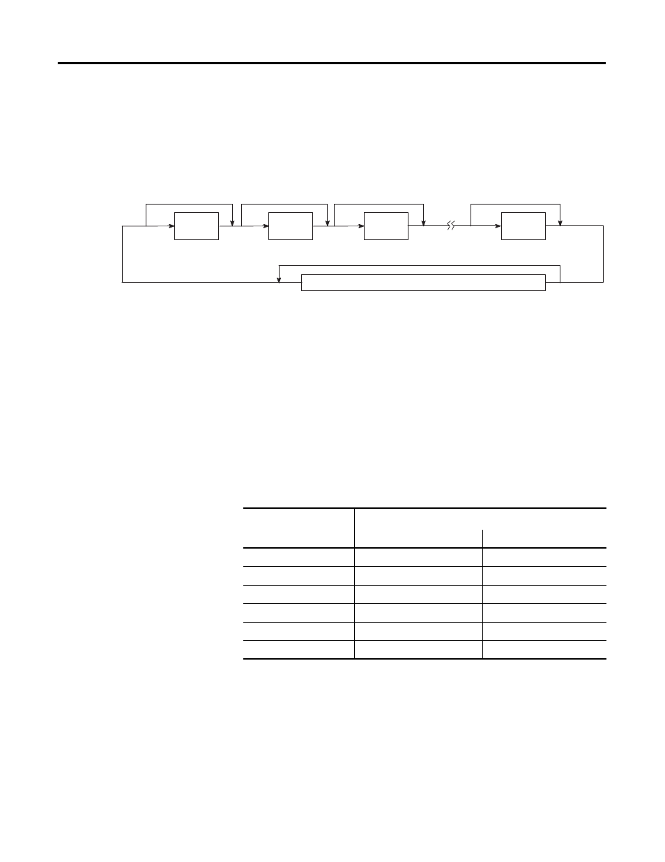
The module update time is defined as the time required for the module to
sample and convert the input signals of all enabled input channels and provide
the resulting data values to the processor. The module sequentially samples the
channels in a continuous loop as shown below.
Module Update Sequence
Module update time is dependent on the number of input channels enabled,
input filter selection, and whether or not a calibration or lead wire
compensation sequence is in progress.
The fastest module update time occurs when only one channel is enabled with
a 1 kHz filter, with autocalibration and cyclic lead compensation disabled. If
more than one channel is enabled, the update time is faster if all channels use
the fastest filter, as shown in example 1 below. The slowest module update
time occurs when all six channels are enabled with the 10Hz filter.
The following table shows the channel update times for all filter frequencies
assuming that no calibration or lead wire compensation is in progress.
Channel 0 Disabled
Channel 1 Disabled
Channel 2 Disabled
Channel 5 Disabled
Sample
Channel 0
Sample
Channel 1
Sample
Channel 2
Sample
Channel 5
Enabled
Enabled
Enabled
Enabled
Channel X Autocalibration or Lead Wire Compensation Disabled
Channel X Autocalibration or Lead Wire Compensation
Table 18 - Channel Update Time versus Filter Frequency
Filter Frequency
Maximum Channel Update Time
(1)
(1) Update times do not include cyclic calibration or lead wire compensation.
with 1 channel enabled
with 6 channels enabled
10 Hz
303 ms
1818 ms
50 Hz
63 ms
378 ms
60 Hz
53 ms
318 ms
250 Hz
15 ms
90 ms
500 Hz
9 ms
54 ms
1 kHz
6 ms
36 ms