Rockwell Automation 1769-IR6 Compact I/O 1769-IR6 RTD/Resistance Input Module User Manual
Page 40
40
Rockwell Automation Publication 1769-UM005B-EN-P - March 2012
Chapter 3 Installation and Wiring
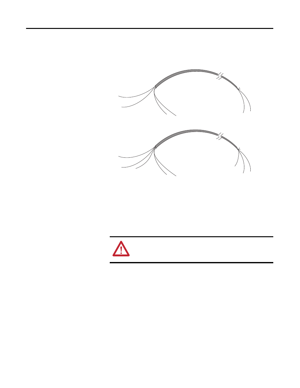
After the module is properly installed, follow the wiring procedure below and
the RTD and potentiometer wiring diagrams on pages 3-41…3-43. To ensure
proper operation and high immunity to electrical noise, always use Belden
shielded, twisted-pair or equivalent wire.
To wire your module follow these steps:
1.
At each end of the cable, strip some casing to expose the individual
wires.
2.
Trim the signal wires to 2-inch (5 cm) lengths. Strip about 3/16 inch
(5 mm) of insulation away to expose the end of the wire.
3.
At the module end of the cable, twist the drain wire and foil shield
together, bend them away from the cable, and apply shrink wrap. Then
earth ground via a panel or DIN rail mounting screw at the end of the
module. Keep the length of the drain wire as short at possible.
4.
At the other end of the cable, cut the drain wire and foil shield back to
the cable and apply shrink wrap.
5.
Connect the signal wires to the terminal block as described for each type
of input. See Wiring RTDs on page 41 or Wiring Resistance Devices
(Potentiometers) on page 42.
6.
Connect the other end of the cable to the analog input device.
ATTENTION:
Be careful when stripping wires. Wire
fragments that fall into a module could cause damage at
powerup.
Cable
Signal Wire
Signal Wire
Drain Wire
Foil Shield
Signal Wire
Signal Wire
Cut Foil Shield
and Drain Wire
Cable
Signal Wire
Signal Wire
Drain Wire
Foil Shield
Signal Wires
Cut Foil Shield
and Drain Wire
Signal Wire