Configuring a 1769-ir6 rtd input module – Rockwell Automation 1769-IR6 Compact I/O 1769-IR6 RTD/Resistance Input Module User Manual
Page 102
102
Rockwell Automation Publication 1769-UM005B-EN-P - March 2012
Appendix B Configuring the 1769-IR6 RTD Module with the Generic Profile
Configuring a 1769-IR6 RTD Input Module
To configure the 1769-IR6 module in slot 1, click on the plus sign left of
Local:1:C. Configuration data is entered under the Local:1:C.Data tag. Click the
plus sign to the left of Local:1:C.Data to reveal the 8 integer data words where
configuration data may be entered for the 1769-IR6 module. The tag addresses
for these 8 words are Local:1:C.Data[0]…Local:1:C.Data[7]. Only the first 6
words of the configuration file apply. The last 2 words must exist but should
each contain a value of 0 decimal.
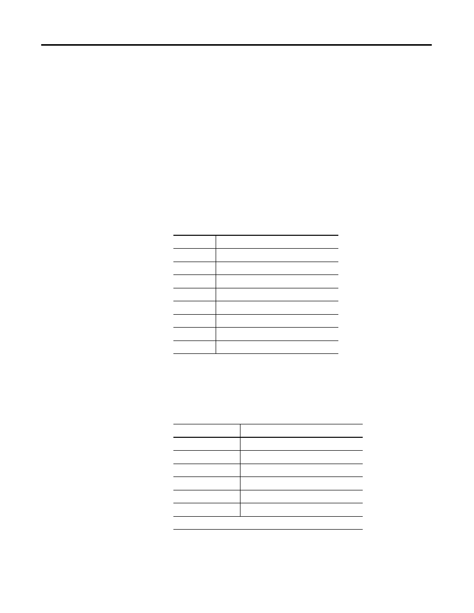
The 6 configuration words, 0…5 apply to IR6 channels 0…5 respectively. All 6
words configure the same parameters for the 6 different channels. The
following shows the various parameters to configure in each configuration
word. For a complete description of each of these parameters and their
possible settings, see Channel Configuration on page 51.
Once you have entered your configuration selections for each channel, enter
your program, save your project, and download it to your CompactLogix
Controller. Your module configuration data is downloaded to your I/O
modules at this time. You 1769-IR6 module input data is located in the
following tag addresses when the controller is in Run mode.
Bit
Parameter
0…2
Filter Frequency
3
Excitation Current Bit
4
Lead Resistance Enable Bit
5 and 6
Broken Input Condition
7
Temperature Units Bit
8…11
Input Type
12…14
Data Format
15
Enable Channel Bit
1769-IR6 Channel
Tag Address
0
Local:1:I.Data[0]
1
Local:1:I.Data[1]
2
Local:1:I.Data[2]
3
Local:1:I.Data[3]
4
Local:1:I.Data[4]
5
Local:1:I.Data[5]
where 1 represents the slot number of the 1769-IR6 module