Rockwell Automation 1771-IL/B , D17716.5.91 ISOLATED ANALOG INPUT Module User Manual
Page 43
Module Calibration
Chapter 6
6-3
4.
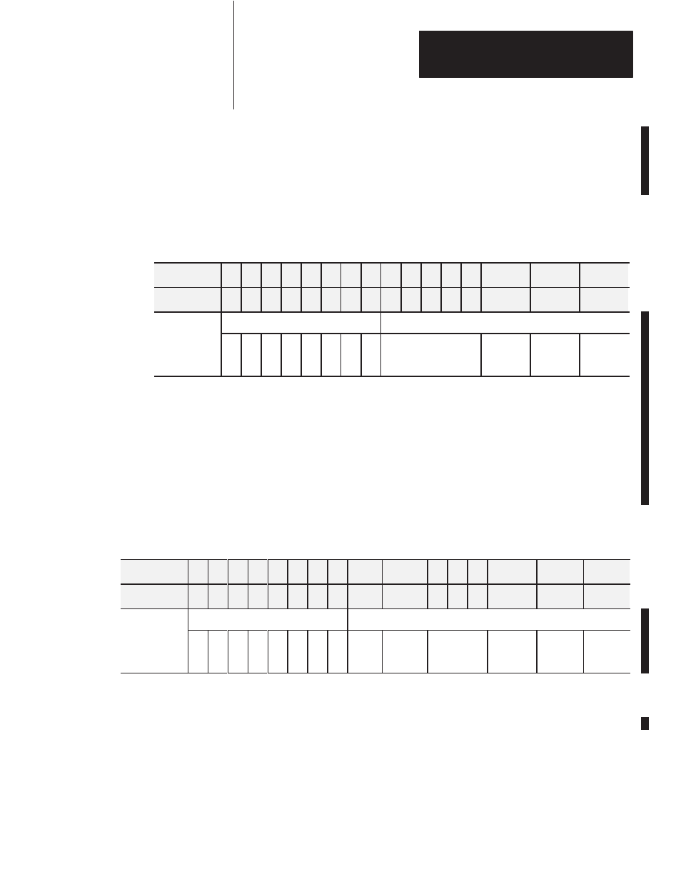
After the connections stabilize, request the offset calibration by setting bit
00 in block transfer write word 37 and sending a block transfer write
(BTW) to the module. Refer to Table 6.A.
When the BTW is sent, all channels are calibrated to 0.00000V.
Table 6.A
Write Block Transfer Word 28
Decimal Bit
15 14 13 12 11 10 09 08 07 06 05 04 03
02
01
00
Octal Bit
17 16 15 14 13 12 11 10 07 06 05 04 03
02
01
00
Inhibit Calibration
Requested Auto-Calibration
Word 37
8
7
6
5
4
3
2
1
Set these bits to 0
Requested
Save
Values
Requested
Gain Cal.
Requested
Offset Cal.
NOTE: Normally, all channels are calibrated simultaneously (decimal bits
08-15; octal bits 10-17 of word 37 are 0). To disable calibration on any
channel, set the corresponding bit 08 through 15 decimal, or 10 through
17 octal, of word 37.
5.
Queue block transfer reads (BTRs) to monitor for offset calibration
complete and any channels which may have not calibrated successfully.
Refer to Table 6.B.
Table 6.B
Read Block Transfer Word 13
Decimal Bit
15 14 13 12 11 10 09 08
07
06
05 04 03
02
01
00
Octal Bit
17 16 15 14 13 12 11 10
07
06
05 04 03
02
01
00
Uncalibrated Channels
Auto-Calibration Status
Word 13
8
7
6
5
4
3
2
1
Cal.
Fault
EEPROM
Fault
Not used
Save to
EEPROM
Complete
Gain Cal.
Complete
Offset
Cal.
Complete
6.
Reset bit 00 (0) (requested offset calibration).
7.
Proceed to Gain Calibration below.