Installing the analog module – Rockwell Automation 1771-IL/B , D17716.5.91 ISOLATED ANALOG INPUT Module User Manual
Page 15
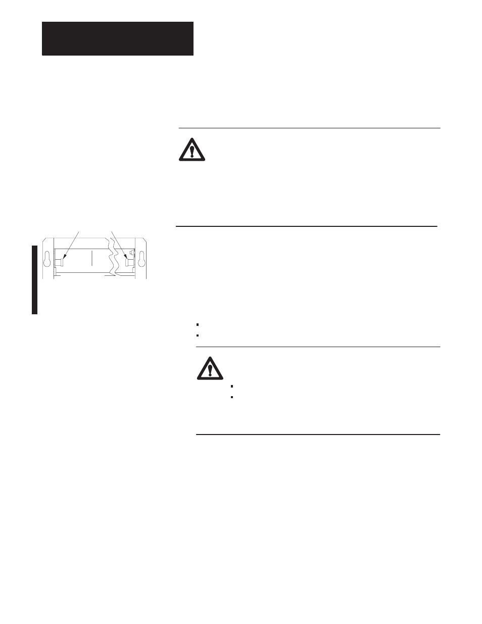
front of chassis
locking-bar pins
12453-I
Installing the Input Module
Chapter 2
2-4
To install your module in an I/O chassis:
1.
First, turn off power to the I/O chassis:
ATTENTION: Remove power from the 1771 I/O chassis
backplane and disconnect the cable from the module before
removing or installing an I/O module.
Failure to remove power from the backplane could cause injury
or equipment damage due to possible unexpected operation.
Failure to remove power from the backplane could cause
module damage, degradation of performance, or injury.
2.
Lift the locking latch holding the module into the chassis. (On chassis
equipped with a chassis locking bar, pull the locking-bar pins to
release the locking bar and swing it up.)
3.
Position the keying bands (Figure 2.2) in the backplane connectors to
correspond to the key slots on the module. This prevents you from
inserting the wrong module in this slot. This analog module uses:
between 10 and 12
between 32 and 34
ATTENTION: Observe the following precautions when
inserting or removing keys:
insert or remove keys with your fingers
make sure that key placement is correct
Incorrect keying or the use of a tool can result in damage to
the backplane connector and possible system faults.
You can change the position of these bands if subsequent system
design and rewiring makes insertion of a different type of module
necessary. Use needlenose pliers to insert or remove keying bands.
Installing the Analog Module