Performing auto-calibration, Offset calibration – Rockwell Automation 1771-IL/B , D17716.5.91 ISOLATED ANALOG INPUT Module User Manual
Page 42
Module Calibration
Chapter 6
6-2
Calibration of the module consists of applying 0.00000V across each input
channel for offset calibration, and +10.00000V across each input channel for
gain correction.
ATTENTION: Verify that each channel’s configuration jumper is
set to the voltage mode (refer to “Setting the Voltage/Current
Selection Jumpers” in chapter 2.) Failure to do so can damage
the module.
Offset Calibration
Normally all inputs are calibrated together. To calibrate the offset of an input,
proceed as follows:
1.
Verify that each channel has its jumper set for voltage mode. (Refer to
“Setting the Voltage/Current Selection Jumper” in chapter 2. Check the
position of the jumper on each channel.
2.
Apply power to the module.
3.
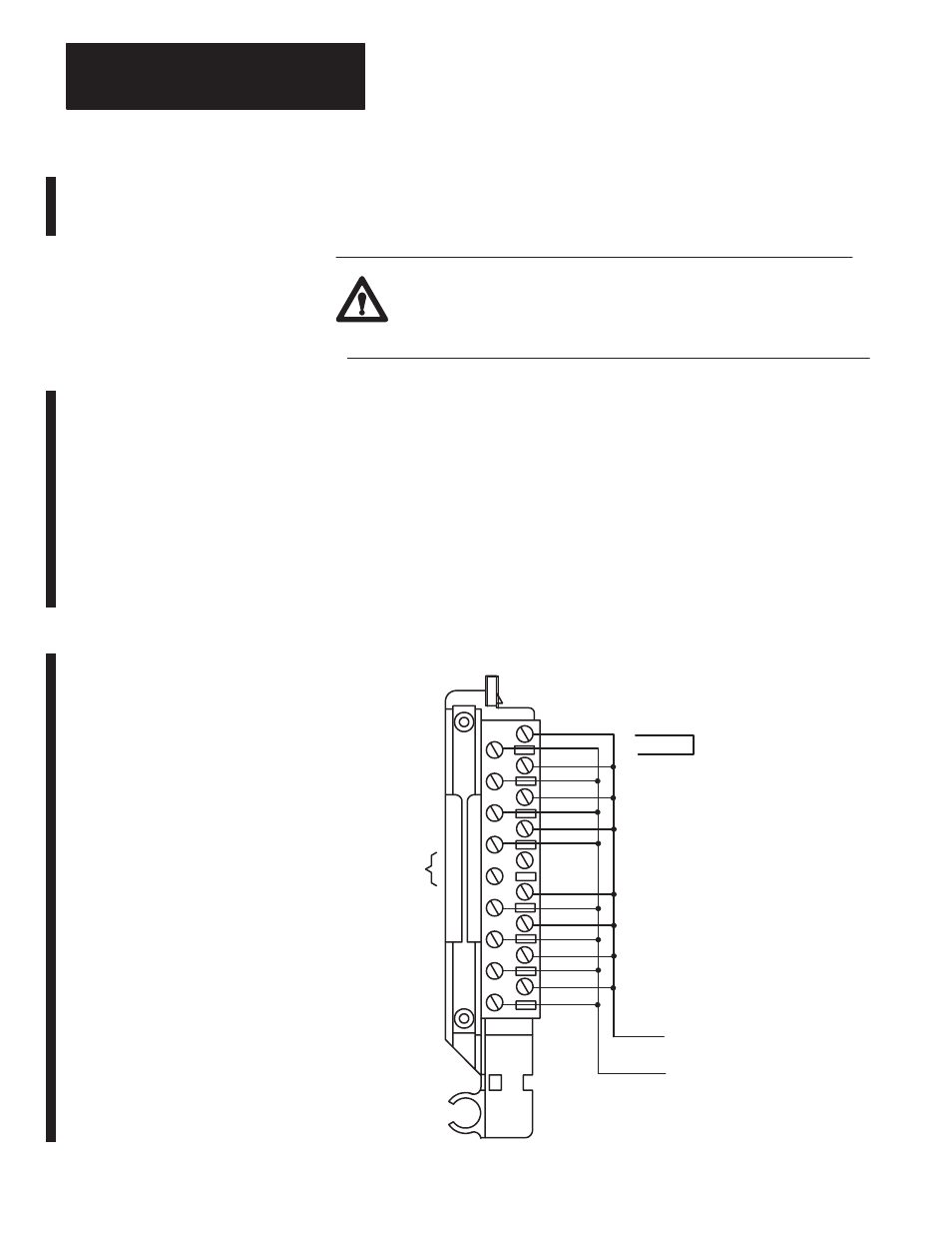
Connect shorting links, or apply 0.00000V across each input channel on
the 1771-WF field wiring arm as shown in Figure 6.1.
Figure 6.1
Shorting Inputs for Offset Calibration
Terminal Identification
Wiring Arm
Cat. No. 1771-WF
Repeat for each channel
Apply
0.00000V
Short each input,
or apply 0.00000V
across each input channel.
Shorting link.
10530-I
18
17
16
1
15
14
13
12
11
10
9
8
7
6
5
4
3
2
18
17
16
15
14
13
12
11
10
9
8
7
6
5
4
3
2
1
Channel 1
Channel 2
Channel 3
Channel 4
Channel 5
Channel 6
Channel 7
Channel 8
Not used
Performing Auto-calibration