Plc-3 programming – Rockwell Automation 1771-IL/B , D17716.5.91 ISOLATED ANALOG INPUT Module User Manual
Page 22
Communicating With Your Module
Chapter 3
3-3
Block transfer instructions with the PLC-3 processor use one binary file in
a data table section for module location and other related data. This is the
block transfer control file. The block transfer data file stores data that you
want transferred to your module (when programming a block transfer
write) or from your module (when programming a block transfer read).
The address of the block transfer data files are stored in the block transfer
control file.
The industrial terminal prompts you to create a control file when a block
transfer instruction is being programmed. The same block transfer
control file is used for both the read and write instructions for your
module. A different block transfer control file is required for every
module.
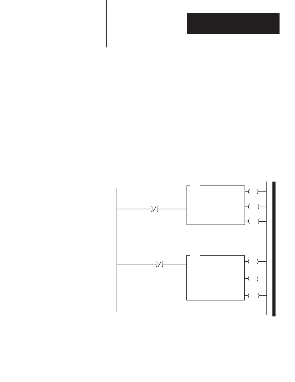
A sample program segment with block transfer instructions is shown in
Figure 3.2, and described below.
Figure 3.2
PLC-3 Family Sample Program Structure
EN
BTR
BLOCK XFER READ
RACK:
GROUP:
MODULE:
DATA:
XXX
X
X = XXXX
XXXX:XXXX
LENGTH:
CNTL:
00
XXXX:XXXX
EN
BTW
BLOCK XFER WRITE
RACK:
GROUP:
MODULE:
DATA:
XXX
X
X = XXXX
XXXX:XXXX
DN
LENGTH:
CNTL:
00
XXXX:XXXX
Block Transfer
Read Done Bit
ER
Enable
Done
Error
12
15
13
Enable
Done
Error
02
05
03
Block Transfer
Write Done Bit
1
2
DN
ER
Program Action
At power-up, the user program enables a
block transfer read. Then it initiates a block
transfer write to configure the module.
Thereafter, the program continuously
performs read and write block transfers.
PLC-3 Programming