Rockwell Automation 1772-LV Mini-PLC - 2/15 Programmable Controller (Series B) Programming and Operations User Manual
Page 95
Advanced Instruction Set
Chapter 6
6Ć38
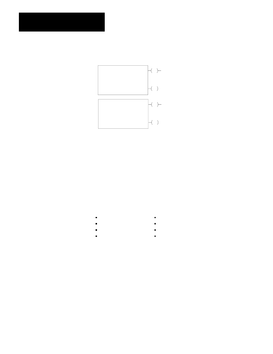
Figure 6.15
Block Transfer Format
EN
Block Xfer Read
Data Addr:
Module Addr:
Block Length:
File:
030
100
01
110 110
DN
010
07
110
07
EN
Block Xfer Write
Data Addr:
Module Addr:
Block Length:
File:
030
100
01
110- 110
DN
010
06
110
06
NOTE: Numbers shown are default values. Numbers in shaded areas must be replaced by user-entered values. The number of
default address digits initially displayed (3 or 4) will depend on the size of the data table.
Here is an explanation of each value:
Data Address
: First possible address in the timer/counter accumulated value area of data table.
Module Address
: RGS for R = rack, G = module group, S = slot number.
Block Length
: Number of words to be transferred. (00 can be entered for default value or for 64 words).
File
: Address of first word of the file.
Enable bit -(EN)-
: Automatically entered from the module address. Set on when rung containing the instruction is true.
Done bit -(DN)-
: Automatically entered from the module address. Remains on for 1 program scan following successfule
transfer.
There are several parts to the instruction that need to be explained. They are:
Data Address
Block length
Module
address
File address
Block
length
Enable bit
Module
address
Done bit
Data Address and Module Address
The data address is used to store the module address of the block transfer
module. The data address must be assigned the first available address in the
timer/counter accumulated area of the data table starting at word address 0308.
When more than one block transfer module is used, consecutive data addresses
must be assigned ahead of address for timer and counter instructions.
The module address is stored in BCD by R=rack, G=module group and S=slot
number (concepts from chapter 4). When block transfer is performed, the
processor searches the timer/counter accumulated area of the data table for a
match of the module address.
The boundary word data bits can be set manually using bit manipulation
[SEARCH] [5][3], or by get/put transfer. The get/put transfer can be