Rockwell Automation 1772-LV Mini-PLC - 2/15 Programmable Controller (Series B) Programming and Operations User Manual
Page 14
An Introduction to Programmable
Controllers
Chapter 2
2Ć7
Picture memory as a page that has been divided into many blocks. Each block
represents one bit. you now know that each bit is either on or off. We could
show the state of each bit by writing “on” or “off” into each block. However,
there is an easier way. We can agree that the numeral one (1) means on and that
the numeral zero (0) means off.
We can easily and quickly show the status of each bit by writing one (1 or zero
(0) into the appropriate block. Most people who work with PCs show bit status
in this way. Frequently, you’ll hear them use expressions like, “The CPU
responded by writing a one into the bit when the limit switch closed.” Of
course, the CPU didn’t really write a one into memory, it simply set the bit by
turning it on.
If you heard the expression, “The CPU wrote a zero into that bit location,” what
actually happened? If you said the CPU merely reset the bit by turning it off,
you’re right. Remember,
When the
I/O device is:
The bit status is
said to be:
on
on
1
set
off
off
0
reset
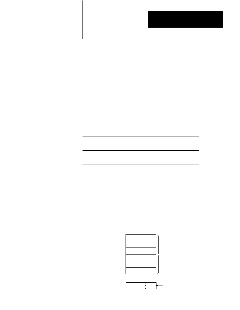
Program Storage
The other major area of memory, program storage, takes up the largest portion
of memory. You’ll recall that this is where your instructions to the
programmable controller are stored. You’ll also recall that this set of
instructions is called a program.
Program Language
A program is made up of a set of statements. Each statement does two things.
First, it describes an action to be taken. For instance, it might say, “Energize
motor starter number one.” Second, it describes the conditions that must exist
in order for the action to take place.
Statement
Statement
Statement
Statement
Statement
Statement
>
Program
Program Storage Area
of Memory
Conditions Action
Program
Statement