Rockwell Automation 1772-LV Mini-PLC - 2/15 Programmable Controller (Series B) Programming and Operations User Manual
Page 184
Quick Reference Section
Appendix A
AĆ15
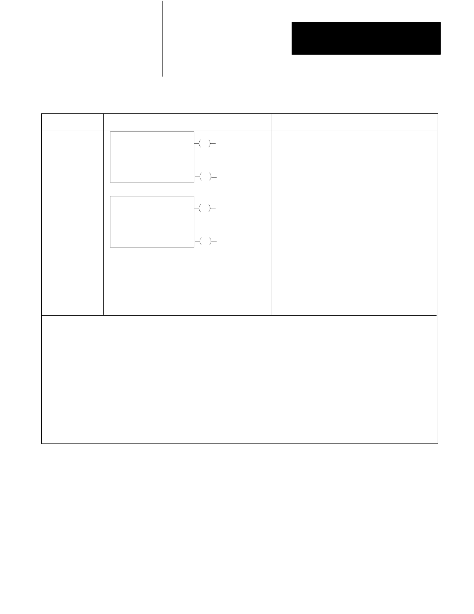
Figure A.3
Block Transfer Instructions
Key Sequence
1770-T3 Display
Instruction Notes
BLOCK XFER
BLOCK XFER
BLOCK XFER
Output instruction.
Block length depends on kind of module.
Entire file transferred in one scan.
Data read from I/O module must be buffered.
Set block lengths equal or to default value for module.
Same module address used for read and write instructions
Enable read and write instructions in same scan.
Order of operation determined by the module.
NOTE: Numbers shown are default values. Numbers in shaded areas must be replaced by your entered values. The number of
default address digits initially displayed (3 or 4) will depend on the size of the data table.
Here is an explanation of each value:
Data Address
Module Address
Block Length
NOTE: Access the Data Monitor Display as follows:
Enter all instruction parameters. Press key sequence:
[DISPLAY] [0] for the binary monitor mode;
[DISPLAY] [1] for the hexadecimal monitor mode.
: First possible address in accumulated value area of data table.
: RGS for R = rack, G = module group, S = slot number.
: Number of words to be transferred. (00 can be entered for default value)
Uses two words of yser program for each instruction.
0
1
0
BLOCK XFER
1
EN
Data Addr:
Module Addr:
Block Length:
030
001
001
DN
File:
110-110
010
06
110
06
Block Xfer Write
EN
Data Addr:
Module Addr:
Block Length:
030
001
001
DN
File:
110-110
010
06
110
06
Block Xfer Read
Enter both instruction blocks for
bidirectional blcok transfer.
Refer to the module user's manual.
File : Address of first word of the file, 100 8 above the data address.