Rockwell Automation 1772-LV Mini-PLC - 2/15 Programmable Controller (Series B) Programming and Operations User Manual
Page 45
Fundamental Instruction Set
Chapter 5
5Ć8
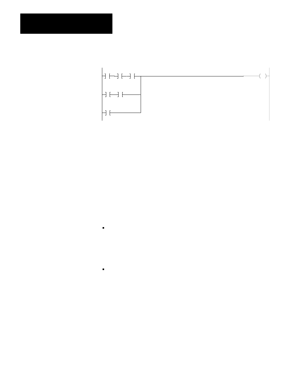
The rung below achieves the same result, but avoids nested branching:
110
00
010
00
110
10
110
11
110
12
110
13
110
11
Section C
Timers and Counters
Timer and counter instructions are output instructions internal to the controller.
They provide many of the capabilities available with timing relays and solid
state timing/counting devices. Usually conditioned by examine instructions,
timers and counters keep track of timed intervals or counted events according to
the logic continuity of the rung. You can program a maximum of 488 internal
timers and/or counters.
Each timer or counter instruction has two 3-digit values. Each value requires
one word of data table memory. These 3-digit values are:
Accumulated
Value
(AC)
Storage: Begins at word address 030.
Function: Timers - number of elapsed timed intervals.
Counters - number of counted events.
Both - upper 4 its of accumulated word (14-17) are the status bits.
Preset
Value
(PR)
Storage: Always 100
8
words greater than its corresponding AC value.
Function: Denotes the number of timed intervals or events to be counted.
When the accumulated value equals the preset value, AC=PR, a status bit is
set and can be examined to turn an output device on or off.
Introduction
A timer counts elapsed time-base intervals and store this count in the
accumulated value word. Timer instructions have three time bases: 1.0 second,
0.1 second, or 0.01 second.
Introduction
Timer/Counter Theory
Timer Instructions