Ać13 – Rockwell Automation 1772-LV Mini-PLC - 2/15 Programmable Controller (Series B) Programming and Operations User Manual
Page 182
Quick Reference Section
Appendix A
AĆ13
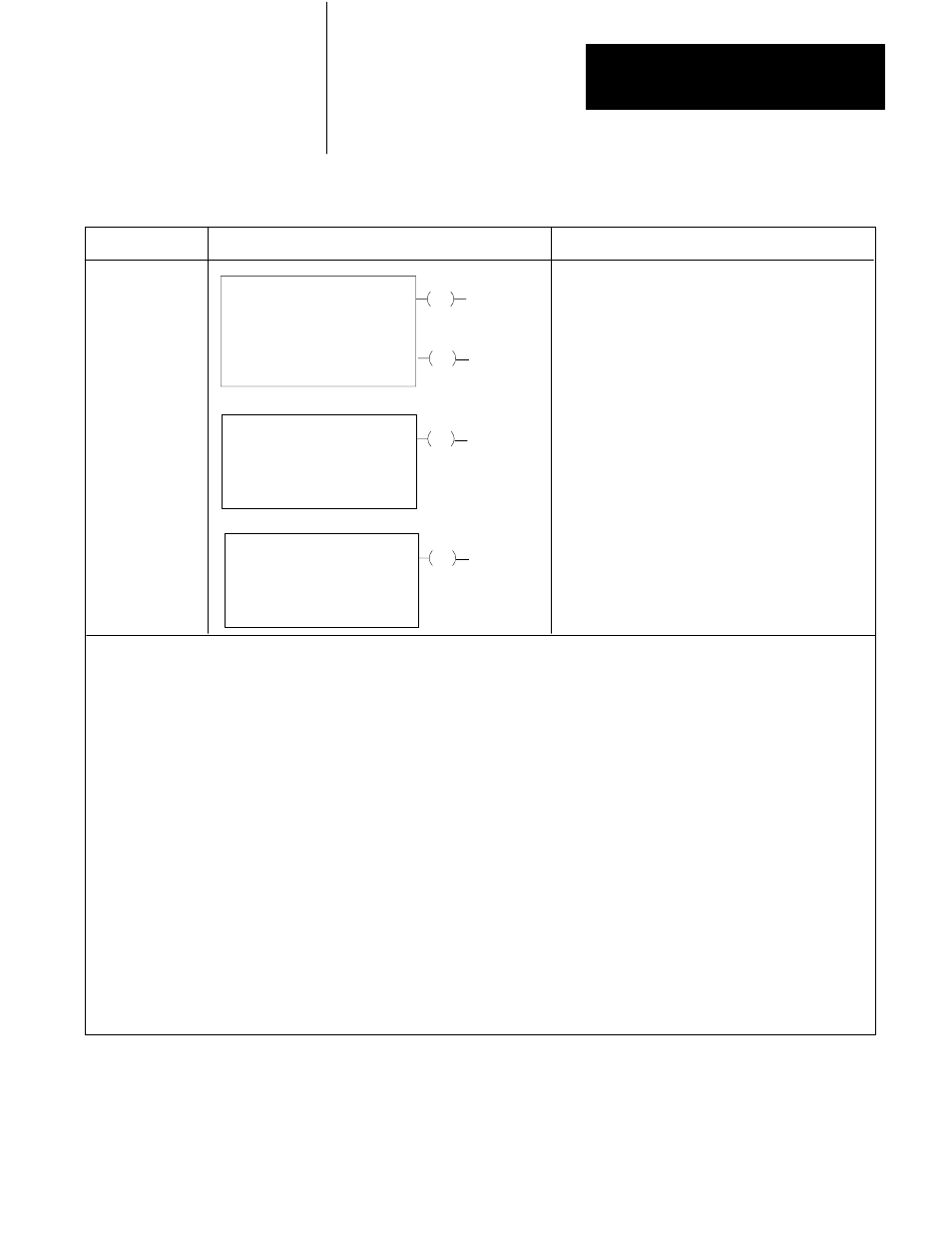
Figure A.1
File Instructions
Key Sequence
1770-T3 Display
Instruction Notes
EN
File To File Move
Counter Addr:
Position:
File Length:
030
001
001
DN
File A:
File R:
Rate Per Scan
110-110
110-110
001
030
17
030
15
Word To File Move
Counter Addr:
Position:
File Length:
030
001
001
DN
File R:
Word Adddress:
110-110
010
030
15
File To Word Move
Counter Addr:
Position:
File Length:
030
001
001
DN
File A:
110-110
030
15
Word Address:
010
FILE
10
FILE
FILE
11
12
Output instruction.
Modes: Complete, istributed and Incremental.
Counter is internally incremented by the instruction.
Requires 5 words of user program.
Output instruction.
Counter must be externally indexed by user program.
Data is transferred every scan that rung is true.
Requires 4 words of user program.
Same as word-to-file.
NOTE: Numbers shown are default values. Numbers in shaded areas must be replaced by user-entered values. The number of
default address digits initially displayed (3 or 4) will depend on the size of the data table.
Here is an explanation of each value:
Counter Address
Position
File Length
File A
File R
Word Address
Rate per scan
NOTE: Access the Data Monitor Display as follows:
Enter all instruction parameters. Press key sequence:
[DISPLAY] [0] for the binary monitor mode;
[DISPLAY] [1] for the hexadecimal monitor mode.
: Address of the instruction in the accumulated value area of data table.
: Curent word being operated upon. (Accumulated value of counter.)
: Starting address of source file.
: Number of words in file (preset value of the counter).
: Starting address of destination file.
: Address of source word or destination word outside of file.
: Number of data words moved per scan.