Controlnet status indicators, Controlnet status indicators -3 – Rockwell Automation 1747-ACNR15 ControlNet Adapter Module User Manual User Manual
Page 89
Publication 1747-UM003A-EN-P
Troubleshooting 5-3
ControlNet Status
Indicators
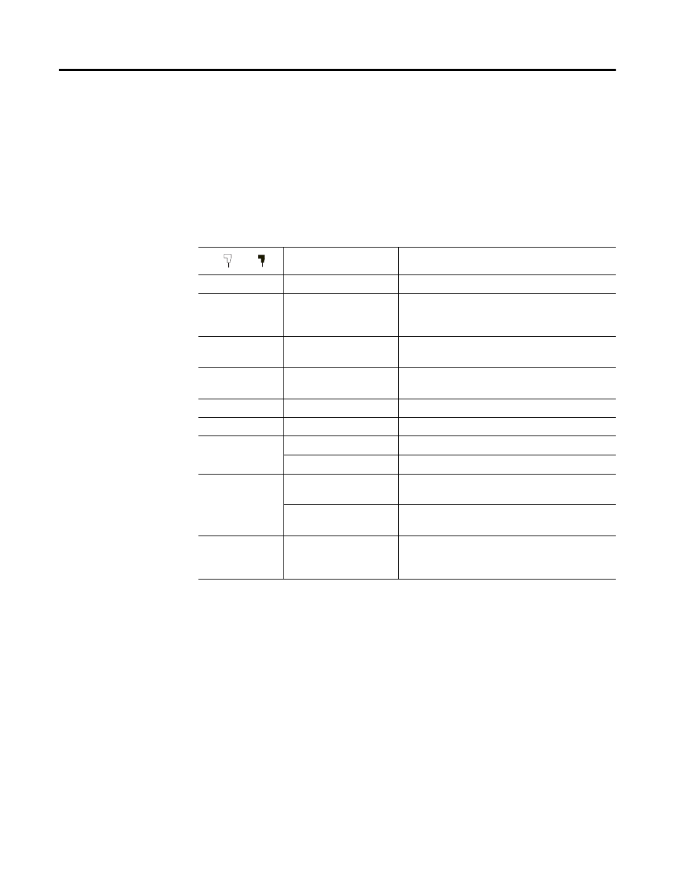
The following table explains module status when indicators are:
•
steady
-
indicator is on continuously in the defined state.
•
alternating - the two indicators alternate between the two defined states at
the same time (applies to both indicators viewed together). The two
indicators are always in opposite states, out of phase.
•
flashing - the indicator alternates between the two defined states (applies to
each indicator viewed independent of the other). If both indicators are
flashing, they must flash together, in phase.
Cause
Action
Off
No power
None or power up
Steady red
Faulted unit
Cycle power
If fault persists, contact Allen-Bradley
representative or distributor.
Alternating red/
green
Self-test
None
Alternating red/
off
Incorrect node
configuration
Check network address and other ControlNet
configuration parameters
Off
Channel disabled
Program network for redundant media, if required
Steady green
Normal operation
None
Flashing green/
off
Temporary errors
None; unit will self-correct
Listen only
Cycle power
Flashing red/off
Media fault
Check media for broken cables, loose connectors,
missing terminators, etc.
No other nodes present
on network
Add other nodes to the network
Flashing red/
green
Incorrect network
configuration
Cycle power or reset unit
If fault persists, contact Allen-Bradley
representative or distributor.
B
A