Rockwell Automation 1747-ACNR15 ControlNet Adapter Module User Manual User Manual
Page 57
Publication 1747-UM003A-EN-P
4-29
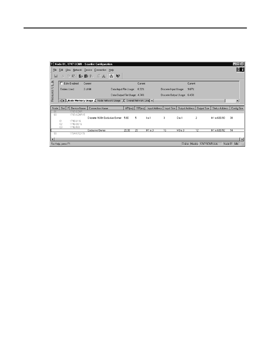
Click Apply, then OK. The Connection Properties window closes and the Scanlist
Configuration window appears and looks like the following:
You have now successfully configured your two connections to read/write
data between the SLC processor and the remote ControlNet chassis. All that
remains is to Save this configuration to the network keeper which, in this case,
is the 1747-SCNR.
Click on the Save icon or choose the File pull-down menu and select Save. You
are
prompted
to
Optimize and re-write schedule for all connections.
Click
OK,
then
click YES to the subsequent warning message. Your network configuration
information is then written to the network keeper.
The display on the front of your 1747-SCNR should show a Full Glass next to
I/O. This indicates that all configured connections were successfully
downloaded to the scanner. In addition, the A and OK LEDs should be solid
green and the B LED should be off, unless you are using the redundant media
option, which is not being used in this example. The 1747-ACN15 should be
displaying that it is active (ACTV) and its LEDs should be solid green for A
and OK and the B LED should be off.