Common power source, Schematic (using ansi/csa symbols) – Rockwell Automation 1747-ACNR15 ControlNet Adapter Module User Manual User Manual
Page 107
Publication 1747-UM003A-EN-P
Understanding Your SLC 500/1746 Control System B-15
Schematic (Using ANSI/CSA Symbols)
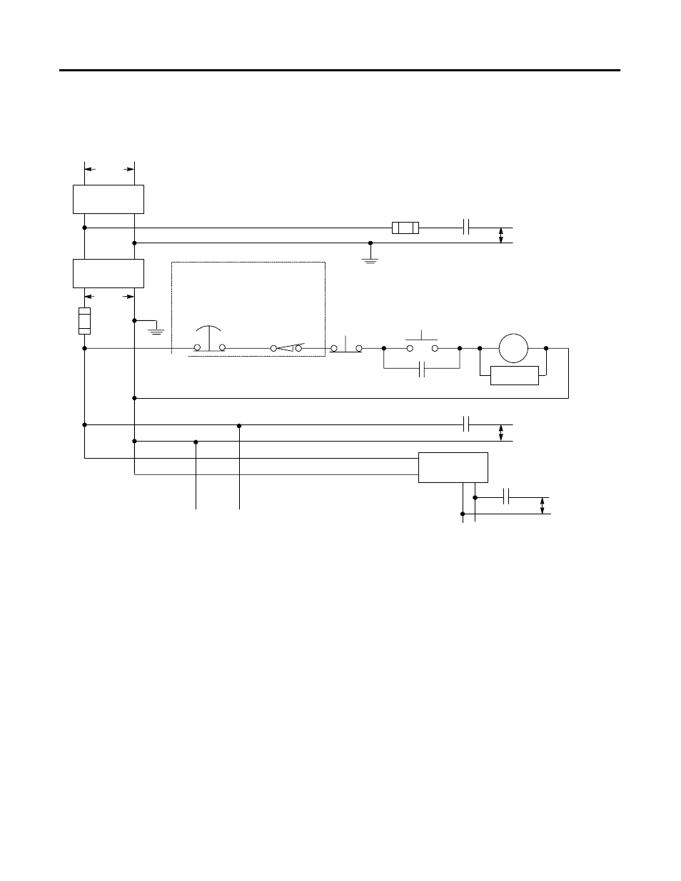
Common Power Source
We strongly recommend that all chassis power supplies have the same power
source as the input and output devices. This helps reduce the chance of
electrical interference due to multiple sources and grounds, as well as maintain
system integrity if power is interrupted.
If you do not use a common power source, you need to apply power to the
expansion chassis before you apply power to the chassis containing the adapter to
avoid an unwanted fault. That is, if the adapter detects the absence of power to any
chassis in the system, the STAT LED turns on and all adapter outputs are
de-energized.
230V ac
L1
L2
Disconnect
Isolation
Transformer
115V ac
X1
X2
Fuse
Fuse
230V ac
Output Circuit
115V ac
Output Circuits
24V dc
Output Circuit
Operation of either of these contacts
removes power from the adapter external
I/O circuits, stopping machine motion.
Emergency-Stop
Push Button
Overtravel Limit
Switch
Stop
Start
Master Control Relay (MCR)
Cat. No. 700-PK400A1
Suppressor Cat. No. 700-N24
MCR
Suppr
MCR
(Lo)
(Hi)
Incoming Line Terminals. Connect to
115V ac terminals of power supply.
dc Power Supply. Use NEC
Class 2 for UL Listing
Incoming Line Terminals. Connect to
24V dc terminals of power supply.
MCR
MCR
MCR