Rockwell Automation 1747-ACNR15 ControlNet Adapter Module User Manual User Manual
Page 41
Publication 1747-UM003A-EN-P
Application Examples 4-13
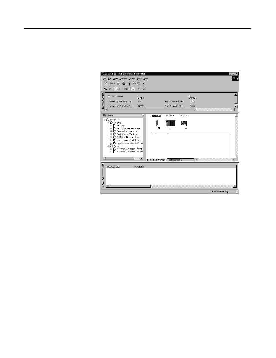
The software attempts to communicate with all possible node numbers on the
network, from 1 to 99. Click the Edits Enabled box to allow changes to be
made. For this example, the on-line network screen should look like the
following, where node 99 is the programming terminal.
Node 1 is the 1747-SCNR and node 3 is the 1747-ACN15. The
1747-ACN15 resides in slot 0 of its chassis, while slot 1 contains a 1746-IA16,
slot 2 contains a 1746-OB16, and slot 3 contains a 1746-NIO4V. For this
example, a single 32-bit rack controller is configured to read/write the three I/
O modules.
Before creating the connection, verify the chassis configuration for the
1747-ACN15 chassis. To do this, right click on the 1747-ACN15, then choose
Edit Chassis. Verify that the chassis configuration is as follows:
slot 0: 1747-ACNR15
slot 1: 1746-IA16
slot 2: 1746-OB16
slot 3: 1746-NIO4V
If the chassis is not already configured, manually configure it by dragging the
appropriate modules from the list on the right to the proper slot on the left of
the chassis configuration screen. When on-line, the software reads the module
types for you. When this is complete, click Apply, then OK.