Calculating the power supply loading – Rockwell Automation 1747-ACNR15 ControlNet Adapter Module User Manual User Manual
Page 127
Publication 1747-UM003A-EN-P
Understanding Your SLC 500/1746 Control System B-35
Once you have determined which way you will calculate the heat dissipation of
your modules, Refer to Example - Worksheet for Calculating Heat Dissipation
on page B-40. This worksheet shows you how to calculate the heat dissipation
for the example 1747-ACN15/-ACNR15 system on Page B-39. Once you feel
comfortable with the layout of the worksheet, go to the worksheet on
Page B-41 and fill it out for your control system.
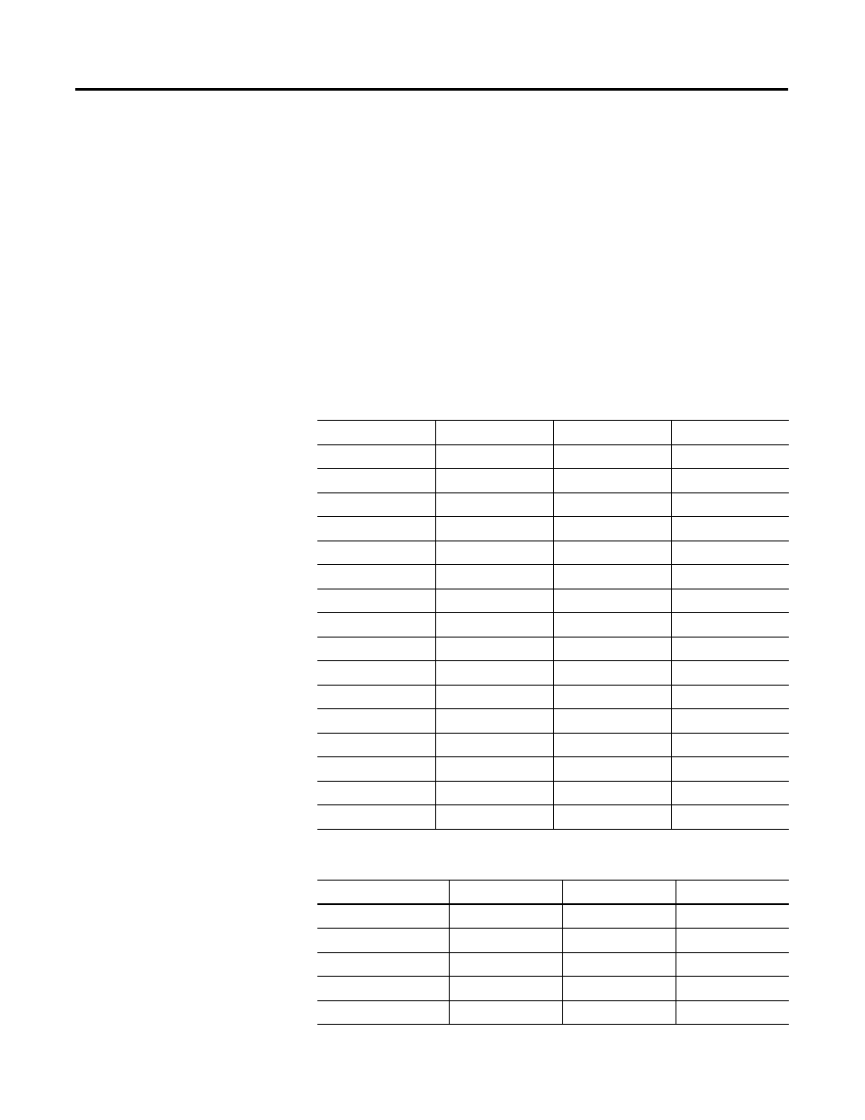
Calculating the Power Supply Loading
Use the tables below to calculate the power supply loading for each chassis that
you have (step 1 of the worksheet).
Table B.5 Input Module Heat Dissipation
Catalog Numbers
Watts per Point
Minimum Watts
Total Watts
1747-IA4
0.27
0.175
1.30
1746-IA8
0.27
0.250
2.40
1746-IA16
0.27
0.425
4.80
1746-IB8
0.20
0.250
1.90
1746-IB16
0.20
0.425
3.60
1746-IC16
0.22
0.425
3.95
1746-IG16
0.02
0.700
1.00
1746-IH16
0.32
0.217
5.17
1746-IM4
0.35
0.175
1.60
1746-IM8
0.35
0.250
3.10
1746-IM16
0.35
0.425
6.00
1746-IN16
0.35
0.425
6.00
1746-ITB16
0.20
0.425
3.60
1746-ITV16
0.20
0.425
3.60
1746-IV8
0.20
0.250
1.90
1746-IV16
0.20
0.425
3.60
Table B.6 Output Module Heat Dissipation
Catalog Numbers
Watts per Point
Minimum Watts
Total Watts
1746-OA8
1.000
0.925
9.00
1746-OA16
0.462
1.850
9.30
1746-OAP12
1.000
1.850
10.85
1746-OB6EI
0.440
0.230
2.90
1746-OB8
0.775
0.675
6.90