Controlnet connectors, Network address switch assemblies – Rockwell Automation 1747-ACNR15 ControlNet Adapter Module User Manual User Manual
Page 11
Publication 1747-UM003A-EN-P
Introducing the ControlNet Adapter Module 1-3
ControlNet Connectors
Cable connection to the module is through standard BNC connectors on the
module frontplate.
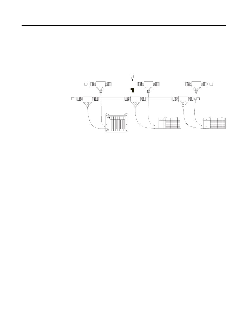
Figure 1.2 Redundant Media System
(1) End device supporting redundant cabling is a 1747-ACNR15.
Refer to the ControlNet Cable System Planning and Installation User Manual,
publication 1786-6.2.1 for more information.
Network Address Switch Assemblies
You must set two switch assemblies to configure your adapter module with its
unique network address. You access these switches through the top of the
module. Figure 1.3 shows the location of the switches. These switches are read
on powerup to establish the network address of the module. Network address
switch settings are described in Chapter 2.
For optimum throughput, assign sequential addresses to ControlNet nodes.
B
A
trunkline A =
trunkline B =
Terminator
Terminator
PLC-5C or SLC 5/02 or later
with 1747-SCNR
end device
(1)
end device
(1)
Terminator
Terminator