Logix assemblies, Pa master input image, Chapter 3 – Rockwell Automation 1788-EN2PAR EtherNet/IP and ControlNet to PROFIBUS PA Linking Device User Manual User Manual
Page 45: Chapter
Rockwell Automation Publication 1788-UM058B-EN-P - September 2014
45
Chapter
3
Logix Assemblies
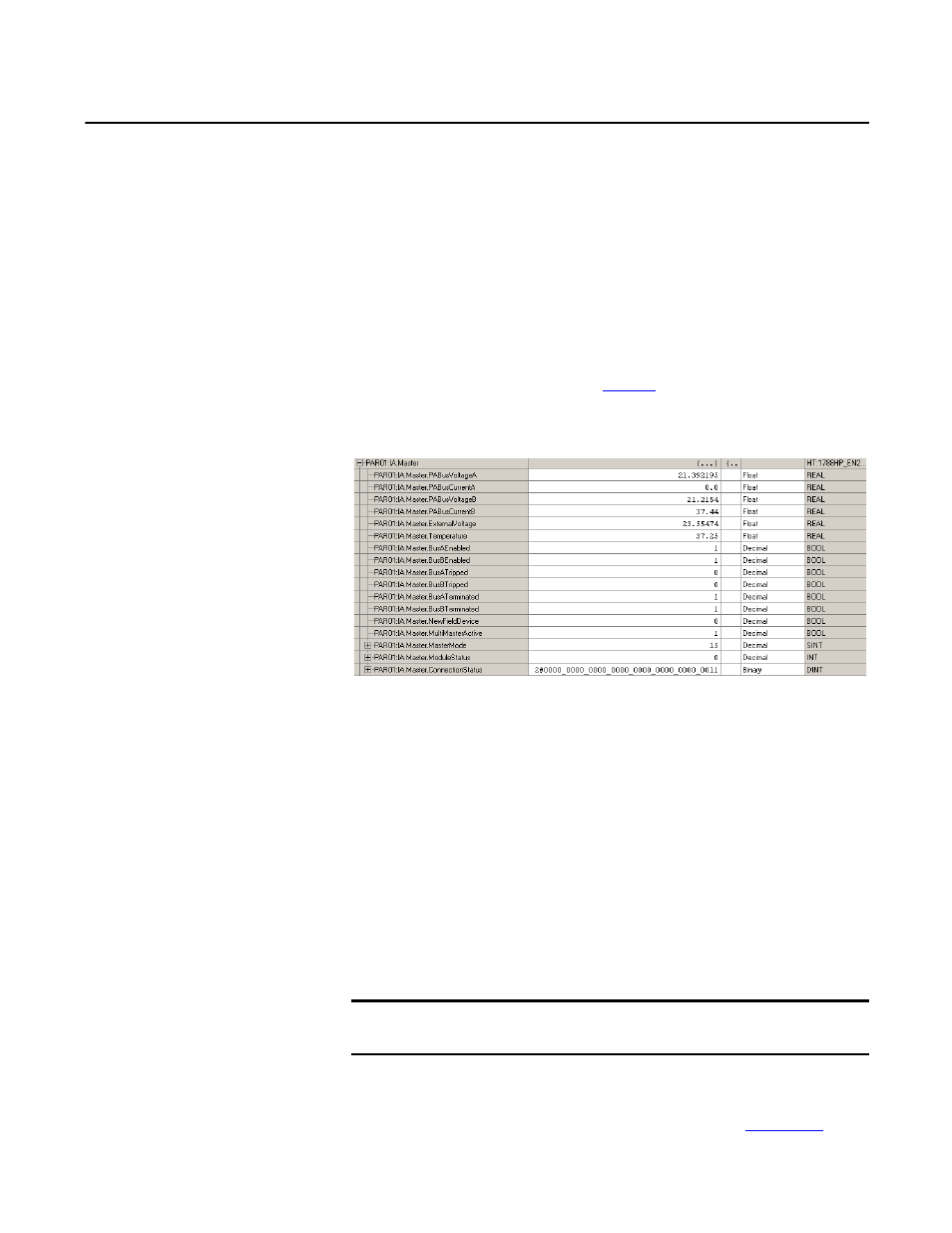
PA Master Input Image
Each linking device uses a total of four connections from the Logix controller,
regardless of the field device count. Therefore, the input and output image of
each linking device is divided into four sections, A through D. Connection A has
the data for the linking device and four field devices. Connections B, C, and D
have the data of four field devices each.
Figure 9
shows the input image of the PA
master.
Figure 9 - PA Master Input Image
Bus A/B Tripped
If too much current is drawn (> 500 mA) on Bus A or Bus B, a trip occurs and the
bus is no longer functional. The trip is indicated in the input image.
NewFieldDevice
This bit is set when a new field device is found that is not in the configuration of
the PA master.
MultiMasterActive
This bit is set after the two PA master modules have synchronized, and they have
the same node number and the same configuration.
MasterMode
This value indicates the currently implemented topology (see
IMPORTANT
Both PA Masters must have the same configuration (master and field devices)
for the masters to be able to synchronize.