Rockwell Automation 1788-EN2PAR EtherNet/IP and ControlNet to PROFIBUS PA Linking Device User Manual User Manual
Page 35
Rockwell Automation Publication 1788-UM058B-EN-P - September 2014
35
Set Up in the Studio 5000 Logix Designer Application
Chapter 2
4.
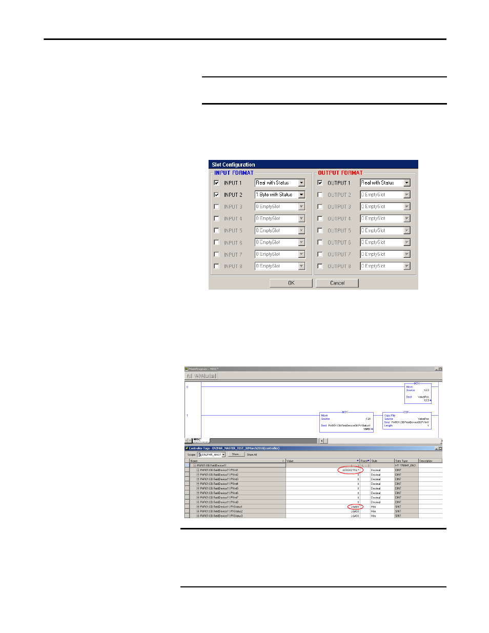
Configure the input and output formats for the slot configuration.
In this example, the setpoint sent to the valve positioner is a real value with
a 1-byte status. The actual position that the valve positioner returns is also
a real value with a 1-byte status, with an added 1 byte with status and
discrete position.
5.
Use the AOP to download the configuration to the linking device. A real
value can now be written into the output PV tag for that field device in the
Studio 5000 Logix Designer application (as shown in the following
figure).
IMPORTANT
See the documentation for the valve positioner to verify the correct
data format for each option.
TIP
See example code CN2PAR_FieldDevice_Outputs.ACD.
IMPORTANT
Send a Good/Valid PV status to the field device output. See the field device user
manual for the needed status values. Typically, if you send a PVStatus value of
0x80 (-128), the field device accepts the position that is given. If you do not
send a Good/Valid PV status to the field device output, the valve postioner
ignores the position that is supplied and returns to a Safe state.