Cable path, Cable lengths, Cable path cable lengths – Rockwell Automation 1788-EN2PAR EtherNet/IP and ControlNet to PROFIBUS PA Linking Device User Manual User Manual
Page 20
20
Rockwell Automation Publication 1788-UM058B-EN-P - September 2014
Chapter 1
Installation
Cable Path
Do not route the PROFIBUS PA cable near any motors or high-voltage/
high-current cables. Motors and high-voltage/high-current cables can generate
noise that decreases communication signal quality on the PA cable, which can
corrupt PA packets and cause field device timeouts.
Cable Lengths
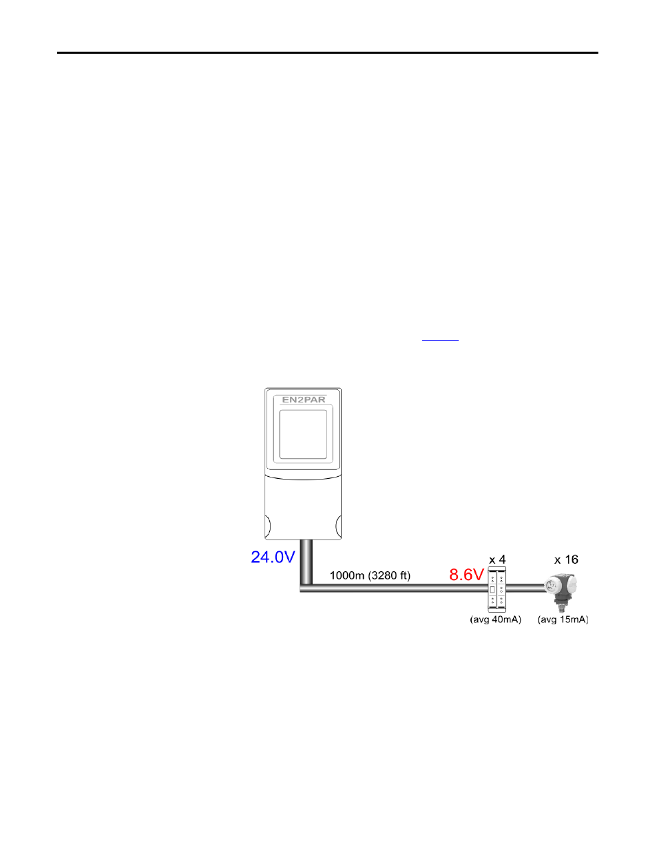
Load and voltage drop determine maximum cable length. Consider these factors
when planning the cable length for your installation:
•
The more field devices and junction boxes that are connected, the bigger
the load will be. The bigger the load, the more the signal attenuates, which
can cause the signal to become unreadable.
•
The bigger the load and the longer the cable, the bigger the voltage drop
across the cable. The voltage at the end of a long cable can drop below the
allowed PROFIBUS PA level. See
Figure 1
for a cable length calculation
example.
Figure 1 - Cable Length Calculation Example
DC resistance per conductor:
24
Ω/km
Total cable resistance:
48
Ω
Total current consumption:
(4 x 40 mA) + (16 x 15 mA)
= 320 mA
Total voltage drop:
48
Ω x 320 mA
=
15.36V