Electrical terminations, Accessing terminations – Rockwell Automation 1608P-200A480V... HC-DySC User Manual User Manual
Page 9
Rockwell Automation Publication 1608P-UM005A-EN-P - November 2014
9
Installation
Chapter 2
Electrical Terminations
Use a qualified electrician to install the HC-DySC in compliance with all local,
and national electric codes. The HC-DySC input (line) and output (load)
terminals are located behind the left door. Terminal details are shown in
Figure 5
on page 12
.
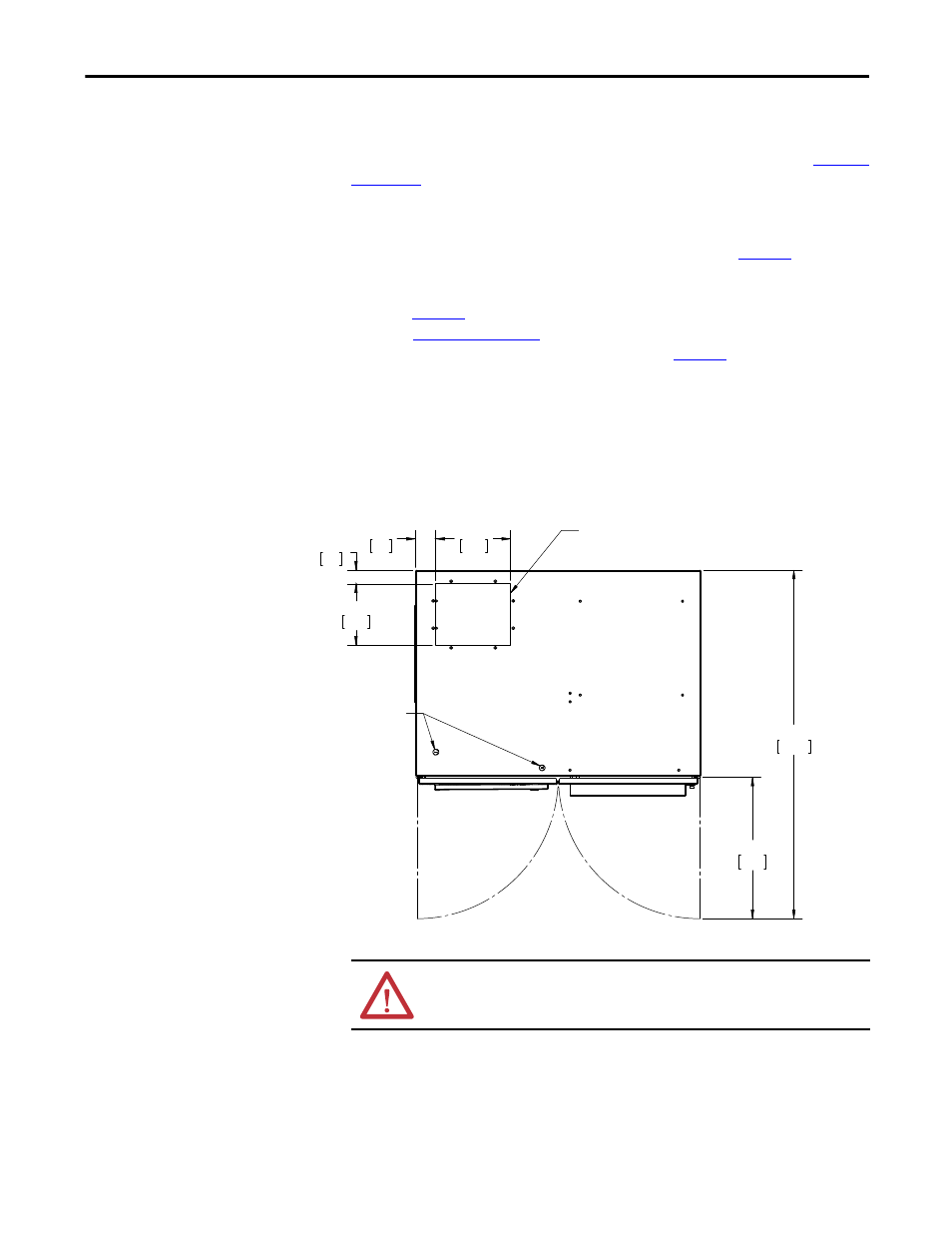
Accessing Terminations
For top entry, remove the top gland plate, which is shown in
Figure 2
, to access
input and output terminals. This plate may be removed for drilling or punching
holes for conduit. Alternate bottom entry should utilize the bottom gland plate
shown in
Figure 1
. Access to the communications port is above the front doors, as
shown in
Figure 6 on page 13
. A separate conduit knock-out is provided for top
entry of communications conductors, as shown in
Figure 2
.
Note:
When punching or drilling holes for conduit fittings, take care to avoid
dropping metallic particles inside the enclosure. Metallic contamination voids
the product warranty.
Figure 2 - Top Conductor Entry
3.00
76
11.00
279
2.00
51
9.00
229
20.75
527
51.07
1297
Area
Recommended
For Top
Conduit Entry
(Shown Without
Cover)
I/O Knockouts
WARNING: Metallic Particles inside the Enclosure Void the Warranty