Electrical terminations and ratings – Rockwell Automation 1608P-200A480V... HC-DySC User Manual User Manual
Page 12
12
Rockwell Automation Publication 1608P-UM005A-EN-P - November 2014
Chapter 2
Installation
Electrical Terminations and
Ratings
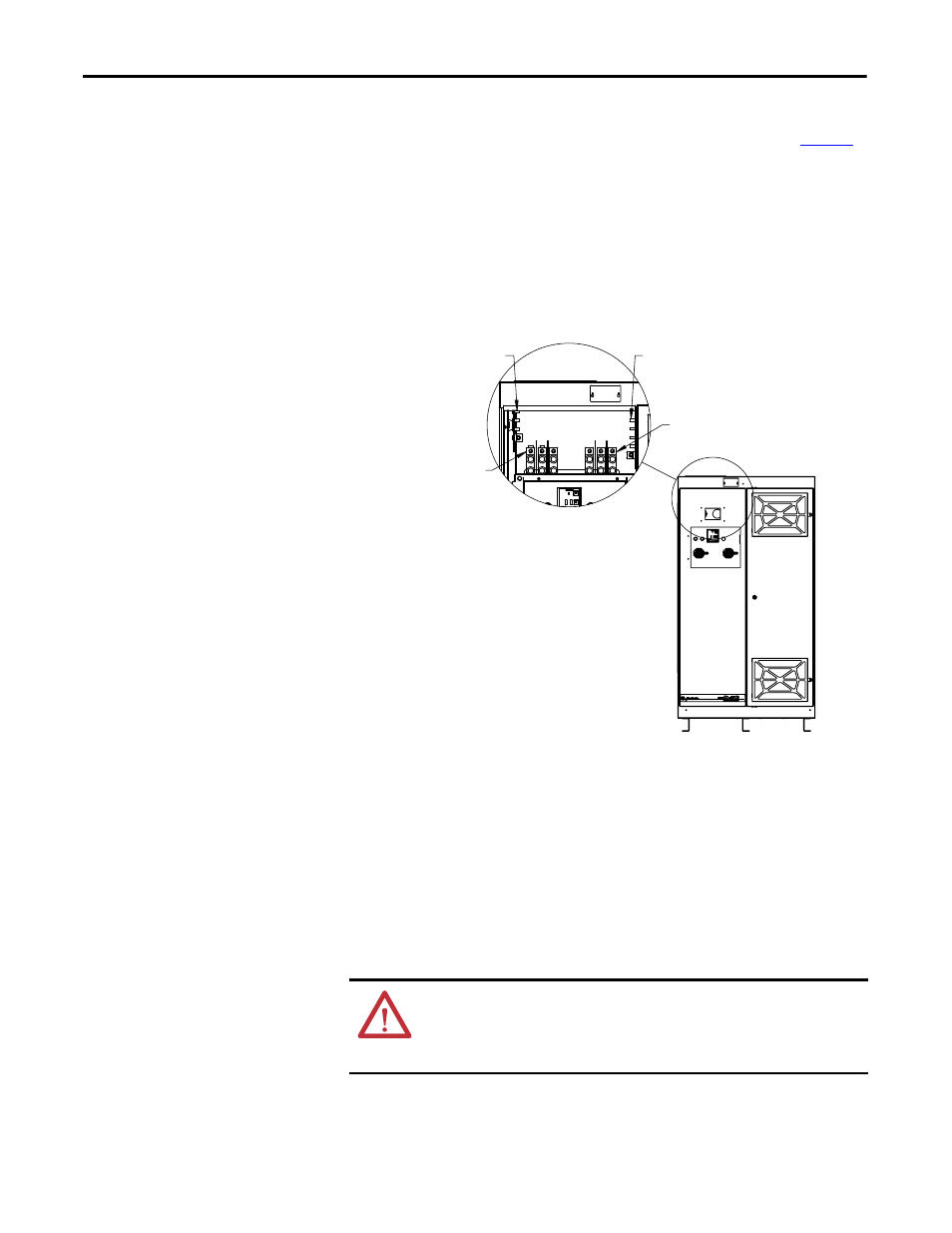
Input connections are marked L1, L2, and L3 for the source connections. Output
connections are marked X1, X2, and X3 for the load connections (See
Figure 5
).
In 4-wire models only, connect both input and output N conductors to the
NEUTRAL bus bar. Do not connect to the NEUTRAL bus bar in 3-wire
models. Replace all shields and covers when wiring is completed. The doors must
be closed and latched securely.
Figure 5 - Electrical Terminations
• Input/Output mechanical lugs accept AWG 6 to 350 kcmil [16 to 150 mm
2
] conductors. Tighten lugs to
275 lb-in [31 N-m]. Lugs require 5/16” hex key tool for installation.
• Input/Output mechanical lugs may be removed and replaced with pressure (crimp) lugs. Two 1/2” holes (1.75”
spacing) are provided.
• NEUTRAL Bus and Ground Bus are provided with 3/8”-16 threaded studs (9.525mm diameter). Tighten nuts to 25 lb-ft
(300 lb-in) [33.9 N-m].
WARNING: The HC-DySC must be safety-grounded according to the National
Electrical Code. In addition, all local, state, and federal regulations applicable to
the installation of electrical systems and accident prevention regulations must
be strictly observed
Neutral Bus
Ground Bus
AC Input
Connections
AC Output
Connections
SHOWN WITH
DOOR OPEN