Floor mounting, Clearance, Circuit breaker recommendations – Rockwell Automation 1608P-200A480V... HC-DySC User Manual User Manual
Page 8
8
Rockwell Automation Publication 1608P-UM005A-EN-P - November 2014
Chapter 2
Installation
Floor Mounting
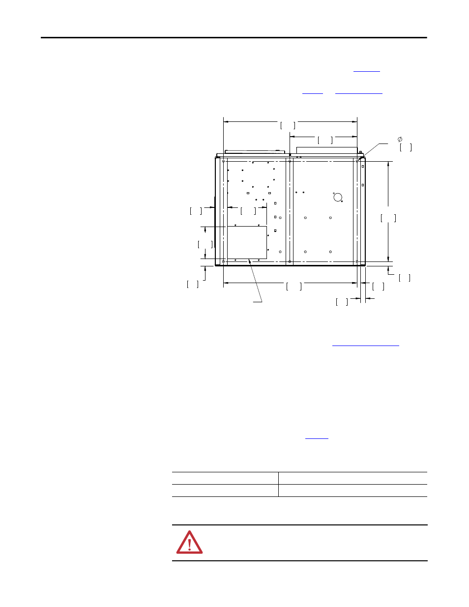
Secure the HC-DySC to the floor using fasteners and fittings appropriate for the
type of floor. Holes are provided in the base channels; see
Figure 1
for mounting
dimensions.
Note: Top or bottom cable entry is allowed. See
Figure 1
and
Figure 2 on page 9
.
Figure 1 - Bottom View Floor Mount Dimensions
Clearance
HC-DySC doors hinge on both right and left. See
Figure 30 on page 40
for
dimensions including door swing. Leave required clearances:
•
Door swing must allow doors to open at least 90°
•
3”[75 mm] on right side for air filter clearance when the door is open
•
Left side clearance is required for bottom entry cable installation
Circuit Breaker
Recommendations
Branch circuit protection upstream of the HC-DySC is required. Maximum
allowed circuit breaker ratings are listed in
Table 1
. Branch circuit protection that
is rated less than the HC-DySC current rating may result in nuisance tripping.
Table 1 - Branch Circuit Protection Ratings
1.38
35
1.00
25
1.20
31
6X
.625
16
2.01
51
9.00
229
11.00
279
3.58
91
37.25
946
28.00
711
37.25
946
18.75
476
Removable Plate for
Bottom Conduit Entry
HC-DySC Rating
Max. MCCB Rating
200 A
250 A
WARNING: To reduce the risk of fire, use only on circuits that are provided with
250 ampere maximum branch circuit protection in accordance with the
National Electric Code ANSI/NFPA 70.