Bypass switch modes, Normal mode, Bypass mode – Rockwell Automation 1608P-200A480V... HC-DySC User Manual User Manual
Page 17
Rockwell Automation Publication 1608P-UM005A-EN-P - November 2014
17
Applying Power and Operation
Chapter 4
Bypass Switch Modes
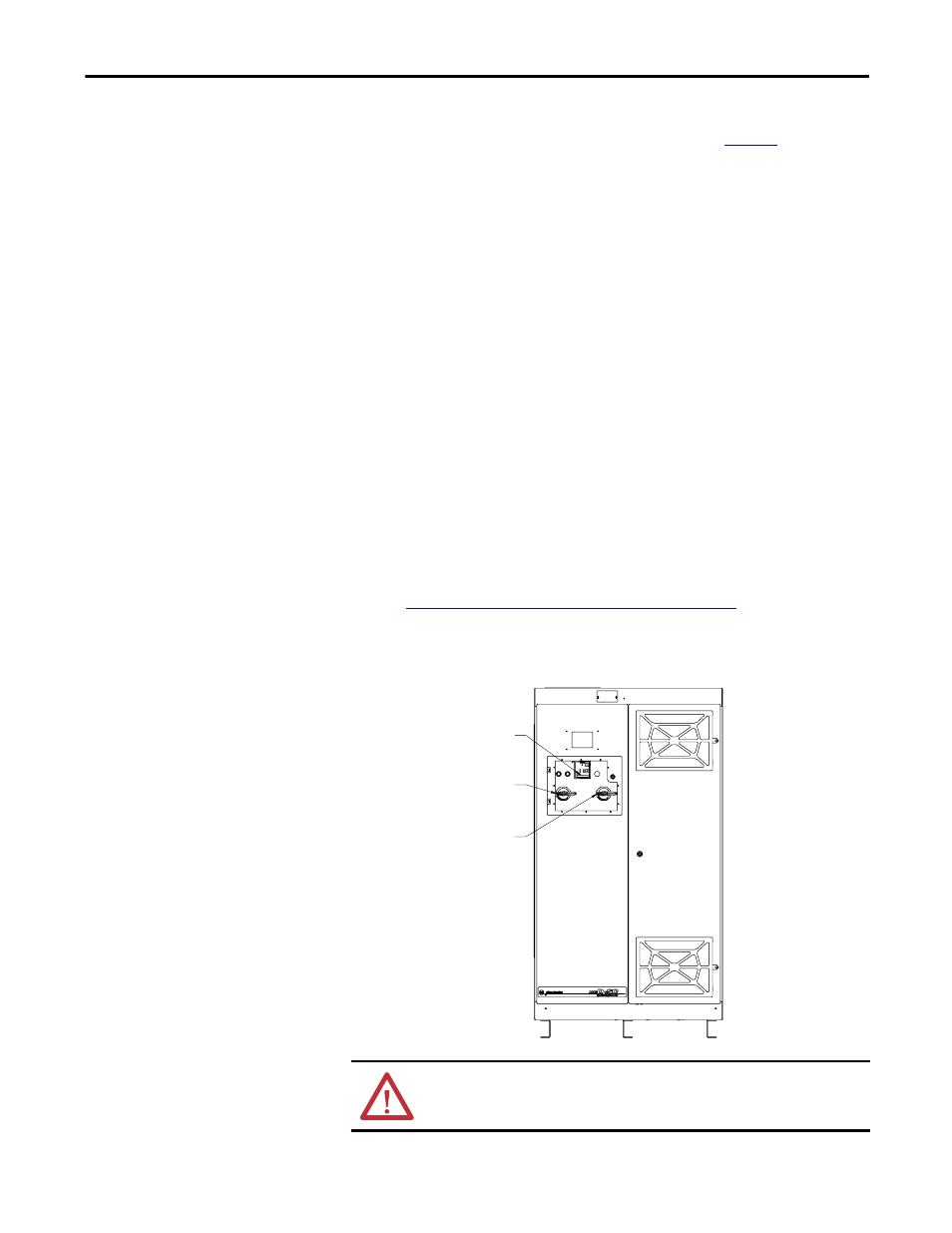
The maintenance bypass switch has three modes of operation: Normal Mode,
Bypass Mode, and Test Mode. It is configured as shown in
Figure 9
.
Normal Mode
The NORMAL mode for the HC-DySC is the input circuit breaker (CBI) and
the output circuit breaker (CBO) closed. The bypass circuit breaker (CBB) must
be open or the HC-DySC will not be able to correct voltage sags. There is a red
indicator light on the enclosure that is lighted when the bypass circuit breaker is
closed. The green "OK" status box should be shown on the touchscreen display.
The green "OK" box indicates that the voltage at the output of the HC-DySC is
within the +10%, -13% normal window. Refer to Table 2 for operational
conditions and indications
Bypass Mode
The BYPASS mode for the HC-DySC is for the input circuit breaker (CBI) and
the output circuit breaker (CBO) to be open. The bypass circuit breaker (CBB)
must be closed to provide power to the load while the HC-DySC is being
serviced.
Refer to
Maintenance Bypass Transfer Procedure on page 18
for instructions on
transferring the system into and out of bypass mode.
Figure 9 - Maintenance Bypass Switch Configuration.
WARNING: Servicing must only be performed by factory authorized and
qualified personnel
CBB
CIRCUIT
BREAKER
CBI
CIRCUIT
BREAKER
CBO
CIRCUIT
BREAKER