Wire vs. 4-wire configurations, Wire models, Figure 3 – Rockwell Automation 1608P-200A480V... HC-DySC User Manual User Manual
Page 10: Figure 3 - hc-dysc 3-wire configuration
10
Rockwell Automation Publication 1608P-UM005A-EN-P - November 2014
Chapter 2
Installation
3-Wire vs. 4-Wire
Configurations
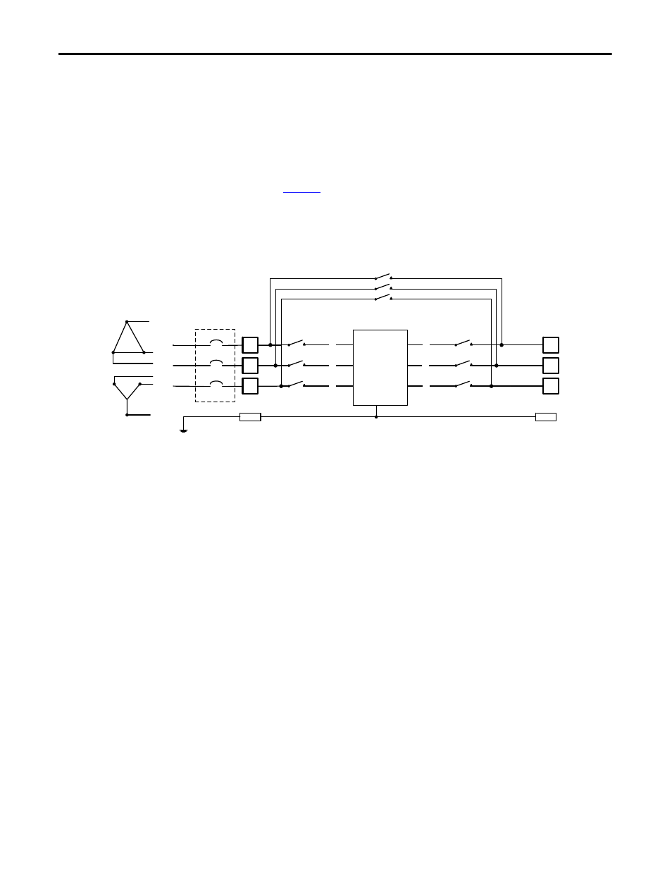
HC-DySC models are available for use with either 3-wire (L1, L2, L3) or 4-wire
(L1, L2, L3, N) sources. The input N conductor must be connected to 4-wire
models for proper operation. Do not connect a N conductor to 3-wire models
.
3- Wire Models
Bulletin 1608P part numbers containing V3 are configured for 3-wire source (L1,
L2, L3) and 3-wire loads (X1, X2, X3). Do not connect a N conductor to 3-wire
models.
Figure 3
shows the 3-wire HC-DySC system wiring schematically,
including the internal maintenance bypass switch
.
Figure 3 - HC-DySC 3-Wire Configuration
Note for Canadian Users: The 200 A HC-DySC models rated greater than 440V have not been
evaluated for compliance with CSA 22.2 No. 107.1-01 when connected to corner-grounded or
ungrounded delta power sources. Contact Rockwell Automation Technical Support for assistance.
L3
X3
X1
X2
L2
CB
CB
CB
Customer supplied
circuit breaker
GND
GND
CBB
CBO
CBI
G
X1
X2
X3
L1
L2
L3
L1
HC-DySC
Electronics
3-WIRE SOURCE