Contactor interlock rod adjustment – Rockwell Automation 1512A MV Controllers, 400A One-High Cabinet, Standard and Arc-Resistant Enclosure User Manual
Page 57
Rockwell Automation Publication 1512A-UM100F-EN-P - May 2013
49
Maintenance
Chapter 5
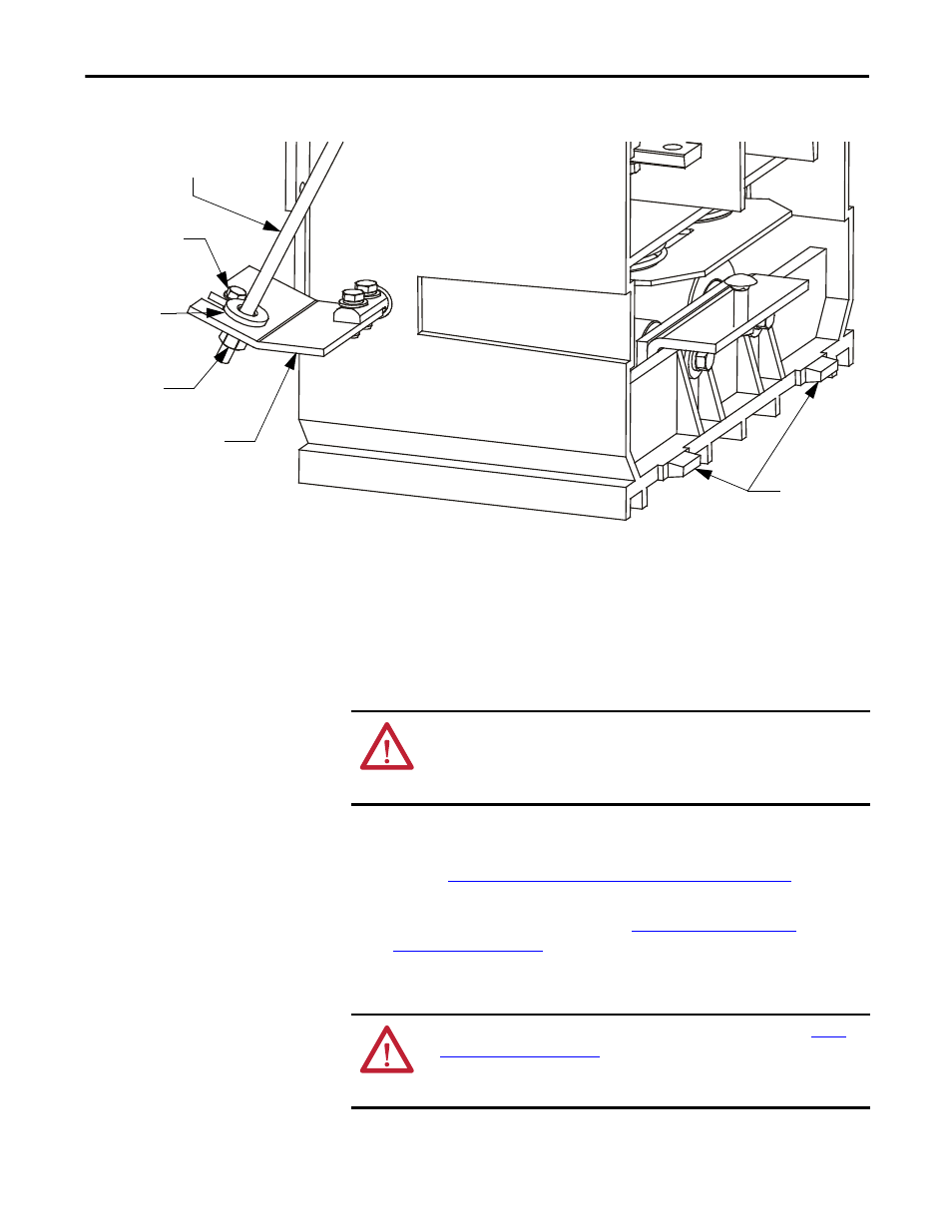
Figure 48 - Removing the Contactor
8. Remove the two contactor mounting bolts at the front of the contactor.
9. Slide the contactor forward slightly to disengage the retaining tabs at the
rear of the contactor from the mounting bracket inside the cabinet.
10. Carefully remove the contactor from the cabinet.
11. If the contactor is being replaced with a new one, move the contactor
interlock lever to the new contactor.
12. Reverse the procedure to reinstall the contactor. Ensure the mounting
bolts, power cable hardware and bus bar hardware is properly torqued.
Refer to
Recommended Torque Values on page 2 of Chapter 1
13. Adjust the contactor interlock rod according to the Contactor Interlock
Rod Adjustment procedure. Refer to
.
Contactor Interlock Rod
Adjustment
Contactor Interlock Rod
Nylon Contactor
Bushing
Retaining Screw
Nylon
Contactor
Bushing
Nyloc Nut
Contactor Operating Lever
Contactor
Remaining Tabs
ATTENTION: The contactor weighs approximately 22 kg (50 lb) and assistance
may be required to safely remove it from the cabinet and transport it. Failure to
use caution when moving the contactor may result in equipment damage
and/or personal injury.
ATTENTION: To avoid shock hazards, lock out incoming power (refer to
) before working on the equipment. Verify with a
hot stick or appropriate voltage measuring device that all circuits are voltage
free. Failure to do so may result in severe burns, injury or death.