Rockwell Automation 1305 AC Drive, Series A and B, Firmware 4.xx-5.xx User Manual
Page 35
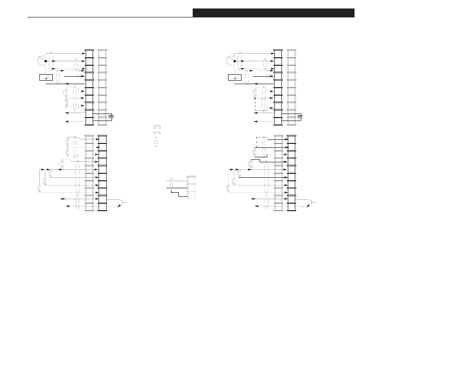
Chapter 2 – Installation/Wiring
2-19
Figure 2.7 Terminal Block (TB2) Designations
[Input Mode] = “Three Wire” or [Input Mode]=“3 w/2nd Acc.”
Figure 2.8 Terminal Block (TB2) Designations – Two Wire
Control Operation
[Input Mode]=“Run Fwd/Rev” or [Input Mode]=“Run F/R 2nd A”
Jumper
Run
Re-
verse
Remote
Pot
1
2
4
5
6
7
8
9
10
0-10 Volts
Source
Wiper or 0-10VDC Input
Common
4-20mA Input
0-10V Output
Common
Stop
Output
#1
Start
Momentary input
Maintained input
Wires must be
shielded
➀
3
Common
Reverse
Jog
Common
SW1
SW2
(Sink)
11
12
13
14
15
16
17
18
19
20
Enable
SW3
Output #2
Remote
Pot
Run
For-
ward
1
2
4
5
6
7
8
9
10
0-10 Volts
Source
Wiper or 0-10VDC Input
Common
4-20mA Input
0-10V Output
Common
Stop
Output
#1
➁
Start
3
Common
Reverse
Jog
Common
SW1
SW2
(Sink)
11
12
13
14
15
16
17
18
19
20
Enable
SW3
Output #2
➄
➀➃
24VDC Source
(User Supplied)
Customer Side
Customer Side
24VDC Source
(User Supplied)
See Table 2.F and notes on page 2-21.
Jumper
Typical for Shield Connections
Shield
Common
(Connect at drive TB2
only)
➂
➂
➂
➂
➂
➂
➂
➂
➂
➂
➂
➂
➂
➂
➂
➂
➀
➀➃
- 20P PowerFlex DC Drive - Frame D Bimetal Thermostat (10 pages)
- 1336S_F_T_E_R F Frame Snubber Resistor Repl. (6 pages)
- 22-COMM PowerFlex 4-Class DSI (Drive Serial Interface) Network Communication Adapter (4 pages)
- 8-545 Plug In Solid State Relay (2 pages)
- 20-HIM-B1 PowerFlex 7-Class HIM Bezel (DPI) (4 pages)
- 100 Contactors with DC Coil (2 pages)
- 100 Contactors with DC Coil (1 page)
- 20P PowerFlex DC Drive - Frame D Switching Power Supply Circuit Board (6 pages)
- 140G-MTFx_MTHx_MTIx_MTKx Trip Unit Installation-140G-M (6 pages)
- 45BRD Analog Laser Sensor (4 pages)
- 20D Multi-Device Interface Option Board for PowerFlex 700S Drives (20 pages)
- 56RF RFID 18 mm Cylindrical Transceiver (2 pages)
- 42KC Miniature Rectangular: 5V DC Version (2 pages)
- 20P PowerFlex DC Drive - Frame A Switching Power Supply Circuit Board (16 pages)
- 21P-MISC-A-TP-2 Transition Tube Kit #C19-6/7 For PowerFlex 755 w/OEM Liquid Cooling Fr 6/7 Drive (2 pages)
- 42BT Background Suppression Sensor (3 pages)
- 42CB High Speed 18mm Cylindrical (4 pages)
- 140EX-JE2_JE3 Molded Case Circuit Breaker (4 pages)
- 140G-K-EAM1A Early Make Aux Contact for Rotary Handle Oper Mech-140G-K (1 page)
- 140G-K-EAM1A Early Make Aux Contact for Rotary Handle Oper Mech-140G-K (3 pages)
- 20-HIM-A6 PowerFlex (Human Interface Module) (74 pages)
- 42CF General Purpose 12mm Cylindrical (4 pages)
- 20D PowerFlex 700S Phase II Drive Frames 1...6 (80 pages)
- 140EX-HE1_HE2 Molded Case Circuit Breaker (6 pages)
- 140EX-HE1_HE2 Molded Case Circuit Breaker (4 pages)
- 20B PowerFlex 700 Custom Firmware - Pump Off (12 pages)
- 20-WIM-N4S DPI Wireless Interface Module (92 pages)
- 140U H-Frame Circuit Breaker Fixed and Adjustable Thermal Trip (2 pages)
- 140U H-Frame Circuit Breaker Fixed and Adjustable Thermal Trip (7 pages)
- 60-2619, 42JS Swivel/Tilt Mounting Bracket (1 page)
- 22A PowerFlex 4/40/400 Flange Mount (4 pages)
- 45MLA Controller Installation Instructions (16 pages)
- 20P PowerFlex DC Drive - Cooling Fan for Frame A Drives Above 73A at 230V 460V AC (6 pages)
- 42JS Series 7000 to 42JS VisiSight Replacement Kit (2 pages)
- 22A PowerFlex 4-Class HIM Bezel (DSI) (4 pages)
- 42CS Stainless Steel Photoelectric Sensors (4 pages)
- 20L-LL PowerFlex 700L Liquid-to-Liquid Heat Exchanger (40 pages)
- 20P PowerFlex DC Drive - Frame B SCR Modules (20 pages)
- 22B PowerFlex 40 Quick Start FRN 5.xx - 6.xx (161 pages)
- 22B PowerFlex 40 Quick Start FRN 5.xx - 6.xx (22 pages)
- 22F PowerFlex 4M Input RFI Filters (2 pages)
- 45LFM Capacitive Label Sensor (4 pages)
- 140G-Rx Installation Instruction-140G-R (2 pages)
- 140G-Rx Installation Instruction-140G-R (29 pages)
- 22C PowerFlex 400 AC Drive Quick Start - FRN 1-4.xx (28 pages)