Rockwell Automation 1336_F_E_T_S SERIES A CHOPPER BRAKE MODULE User Manual
Page 9
Heavy Duty Dynamic Braking
9
1336-5.65 — March, 2007
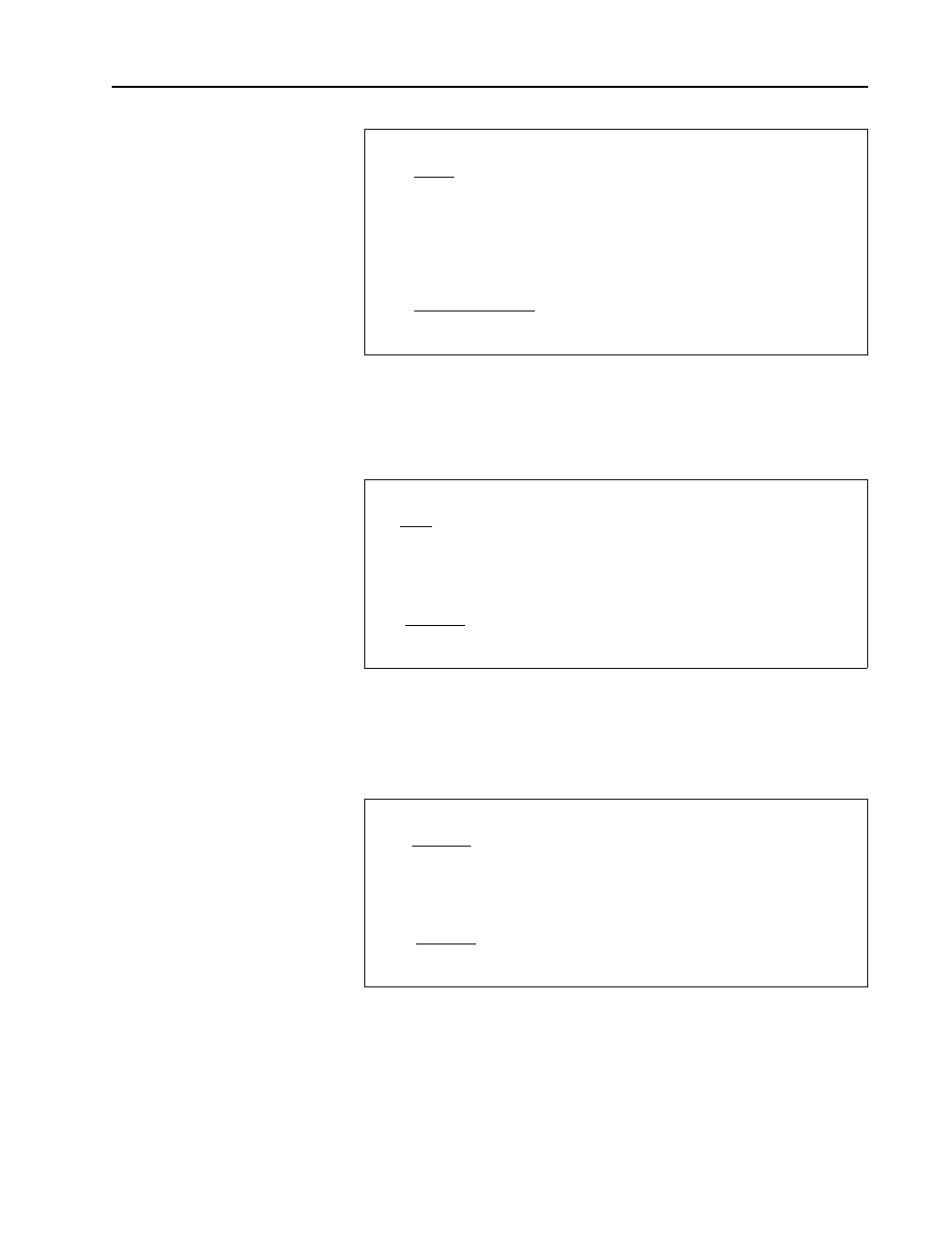
Step 4 — Calculate the Maximum Dynamic Brake Resistance Value
The choice of the Dynamic Brake resistance value should be less than the
value calculated in Step 4. If the resistance value is greater than the value
calculated in Step 4, the drive can trip on DC Bus overvoltage.
Step 5 — Calculate the Minimum Chopper Module Current Rating
The value of I
d1
sets the minimum current rating for the Chopper Module.
When choosing a Chopper Module, the current rating for the Chopper
Transistor must be greater than or equal to the value calculated for I
d1
.
Step 6 — Calculate the Minimum Dynamic Brake Resistor Value
This step calculates the minimum resistance value that the Dynamic Brake
Resistor can have. If a lower resistance were to be used with the Chopper
Module of choice, the IGBT could be damaged from overcurrent.
R
db1
=
R
db1
= Maximum allowable value for the dynamic brake
resistor (ohms)
V
d
= DC Bus voltage the chopper module regulates to
(375V DC, 750V DC, or 937.5V DC)
P
b
= Peak braking power calculated in Step 2 (watts)
V
d
2
P
b
R
db1
=
[
✕
]
[
]
R
db1
= _________ ohms
I
d1
=
I
d1
= Minimum current flow through Chopper Transistor
V
d
= Value of DC Bus voltage chosen in Step 3
R
db1
= Value of Dynamic Brake Resistor calculated in Step 3
V
d
R
db1
I
d1
=
[
]
[
]
I
d1
= __________ amps
R
db2
=
R
db2
= Minimum ohmic value of the Dynamic Brake Resistor
V
d
= Value of DC Bus voltage chosen in Step 3
I
d2
= Value of Chopper Module current rating
V
d
0.75
✕
I
d2
R
db2
=
[
]
[
]
R
db2
= __________ ohms