Wa018, wb009 and wc009 single brake wiring scheme, Heavy duty dynamic braking 31 – Rockwell Automation 1336_F_E_T_S SERIES A CHOPPER BRAKE MODULE User Manual
Page 31
Heavy Duty Dynamic Braking
31
1336-5.65 — March, 2007
L1
L2
L3 +DC -DC
TB1
Drive
TB3
MOD-L6 or MOD-L3
Option
20
STOP
19
START
START
115V AC
21
COM
22
23
24
25
COM
26
27
28
29
COM
30
ENABLE
STOP
CUSTOMER
ENABLE
2
(+) DC BUS
1
(–) DC BUS
4
(+) SLAVE IN
3
(–) SLAVE IN
6
EXT RESISTORS
9
AUX CONT
10
AUX CONT
TB1
Master Brake
➍
5
EXT RESISTORS
7
(+) MASTER OUT
8
(–) MASTER OUT
➌
➊
➎
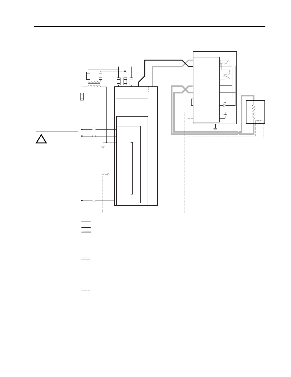
-BRK
-DC Brake Power Wiring
+DC Brake Power Wiring
Brake Resistor Wiring
All Brake Power and Brake Resistor
Wiring must be twisted wire run in conduit
separate from Control Wiring. Size wire
according to NEC and local guidelines.
Control Wiring
All Control Wiring must be twisted wire run in
conduit separate from DC Brake Power Wiring.
Interconnection Control Wiring between the brake
terminals must be twisted pair, 1
mm
2
(18
AWG)
minimum.
Typical Brake Fault Contact Wiring
Connect to AUX at TB3 — Terminal 24 for L6 Option
— Terminal 28 for L3 Option.
MASTER OUT terminals are factory jumpered and must
remain jumpered for single brake applications. For
multiple brake applications, remove the jumpers in all
but the last enclosure.
Contact is shown in a de-energized state. Contact is closed
when power is applied and relay is energized. Loss of power or
a brake malfunction will open contact.
➊
➋
➌
Connect the brake frame to earth ground. Refer to the connected drive's User Manual for grounding instructions.
Optional overtemperature switch.
➍
➎
➋
WA018, WB009 and WC009
Single Brake
Wiring Scheme
For Drive Catalog
Numbers:
1336F –
BRF75
BRF100
1336S –
BRF75
BRF100
ATTENTION:
Damage to drives
can result from
improper wiring.
Read drive
nameplate to
confirm catalog
number and rating
code to determine
correct wiring
diagram.
!