Mounting requirements – Rockwell Automation 1336_F_E_T_S SERIES A CHOPPER BRAKE MODULE User Manual
Page 25
Heavy Duty Dynamic Braking
25
1336-5.65 — March, 2007
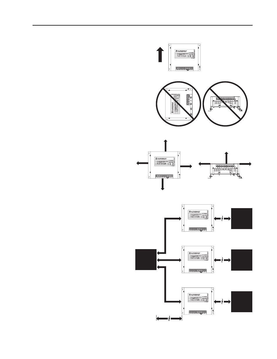
Mounting Requirements
IMPORTANT: The National Electrical Code (NEC) and
local regulations govern the installation and wiring of the
brake chopper modules, dynamic braking resistors and
enclosure selection. DC power wiring, AC power wiring,
control wiring and conduit must be chosen, sized and
installed in accordance with these codes and the
information supplied on the following pages.
Brake chopper modules must only be installed in the
vertical position. Select an enclosure and a location using
the guidelines below and on the following page.
1.
Allow a minimum clearance of 152.4 mm
(6 in.) Between brake modules inside an
enclosure and all other equipment including
the drive. All brake resistor banks should be
mounted external to the enclosure on a non
combustible surface.
2.
If more than one module is required, all
modules must be mounted within 3.0 m (10 ft.)
of the drive. The wires used to connect each
module to the drive must be the same length.
Resistors must be located within 30 m (100 ft.)
of the chopper module. The minimum distance
between each resistor bank and all other
enclosures or equipment is application
dependent and must be determined by the user.
(Front)
(Bottom)
(Front)
Air Flow
GND
(Front)
(Bottom)
152.4 mm
(6 in.)
Minimum
152.4 mm
(6 in.)
Minimum
152.4 mm
(6 in.)
Minimum
152.4 mm
(6 in.)
Minimum
152.4 mm
(6 in.)
Minimum
152.4 mm
(6 in.)
Minimum
152.4 mm
(6 in.)
Minimum
Drive
Resistor
Bank
3.0 m
(10 ft.)
Maximum
30 m
(100 ft.)
Maximum
Resistor
Bank
30 m
(100 ft.)
Maximum
Resistor
Bank
30 m
(100 ft.)
Maximum
Each of these wires must
be of equal length.