Procedure (cont.), Start and run boost settings appendix a, Typical low hp curve – Rockwell Automation 1336VT AC DRIVE 5-300AMP (2-160KW) PROGRAMMING MANUAL User Manual
Page 85: Typical high hp curve
Start and Run Boost Settings
Appendix A
A-3
Procedure (cont.)
75%
Drive Output Current
25%
Drive Output Current
50%
Drive Output Current
100%
Drive Output Current
3
6V
2
0V
4
12V
5
18V
6
24V
7
30V
8
36V
9
42V
10
48V
Parameter 9 =
DC Boost =
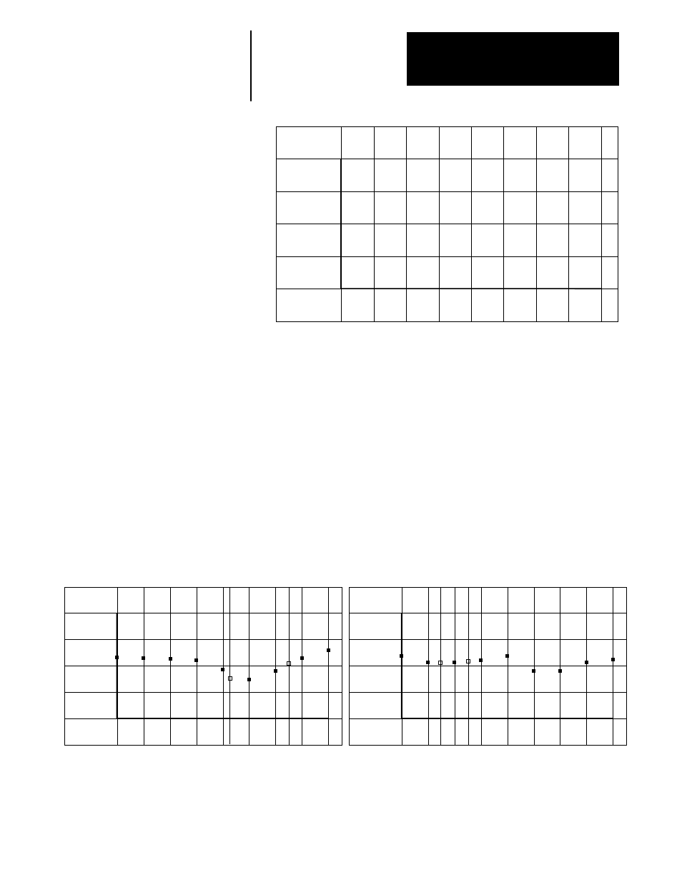
3. Once smooth acceleration is obtained, set DC boost (Parameter 9) to 2,
then 3, 4, 5, 6, 7, 8, 9 and finally 10. Monitor and record drive output
current (Parameter 2) at each setting in the graph above. Compare the
values to those provided in the graph below.
•
If boost voltage is too low, the motor will be under excited and not be
able to develop full torque.
•
If boost voltage is too high, motor windings may saturate and cause
difficulty in starting.
•
The optimum setting for developing high motor torque is shown in
the graphs below.
75%
Drive Output Current
25%
Drive Output Current
50%
Drive Output Current
100%
Drive Output Current
3
6V
2
0V
4
12V
5
18V
6
24V
7
30V
8
36V
9
42V
10
48V
Parameter 9 =
DC Boost =
Typical Low HP Curve
1
1 Optimum Setting of Parameter 9
2 Optimum Setting of Parameter 48
3 Optimum Setting of Parameter 83
2
3
75%
Drive Output Current
25%
Drive Output Current
50%
Drive Output Current
100%
Drive Output Current
3
6V
2
0V
4
12V
5
18V
6
24V
7
30V
8
36V
9
42V
10
48V
Parameter 9 =
DC Boost =
Typical High HP Curve
1 Optimum Setting of Parameter 9
2 Optimum Setting of Parameter 48
3 Optimum Setting of Parameter 83
2
3
1